This thread has been locked.

If you have a related question, please click the "Ask a related question" button in the top right corner. The newly created question will be automatically linked to this question.

dsp clkout have no signal

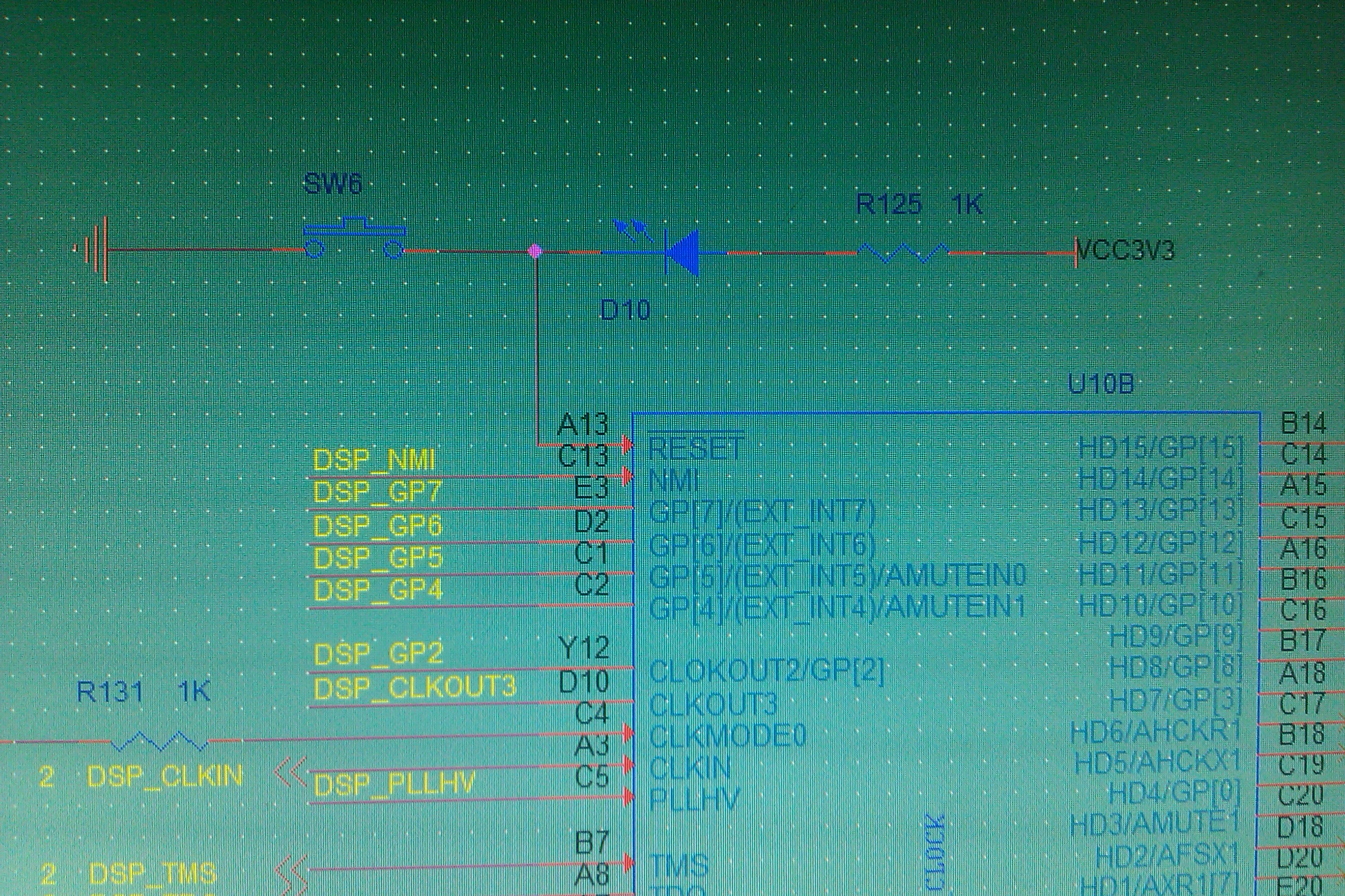
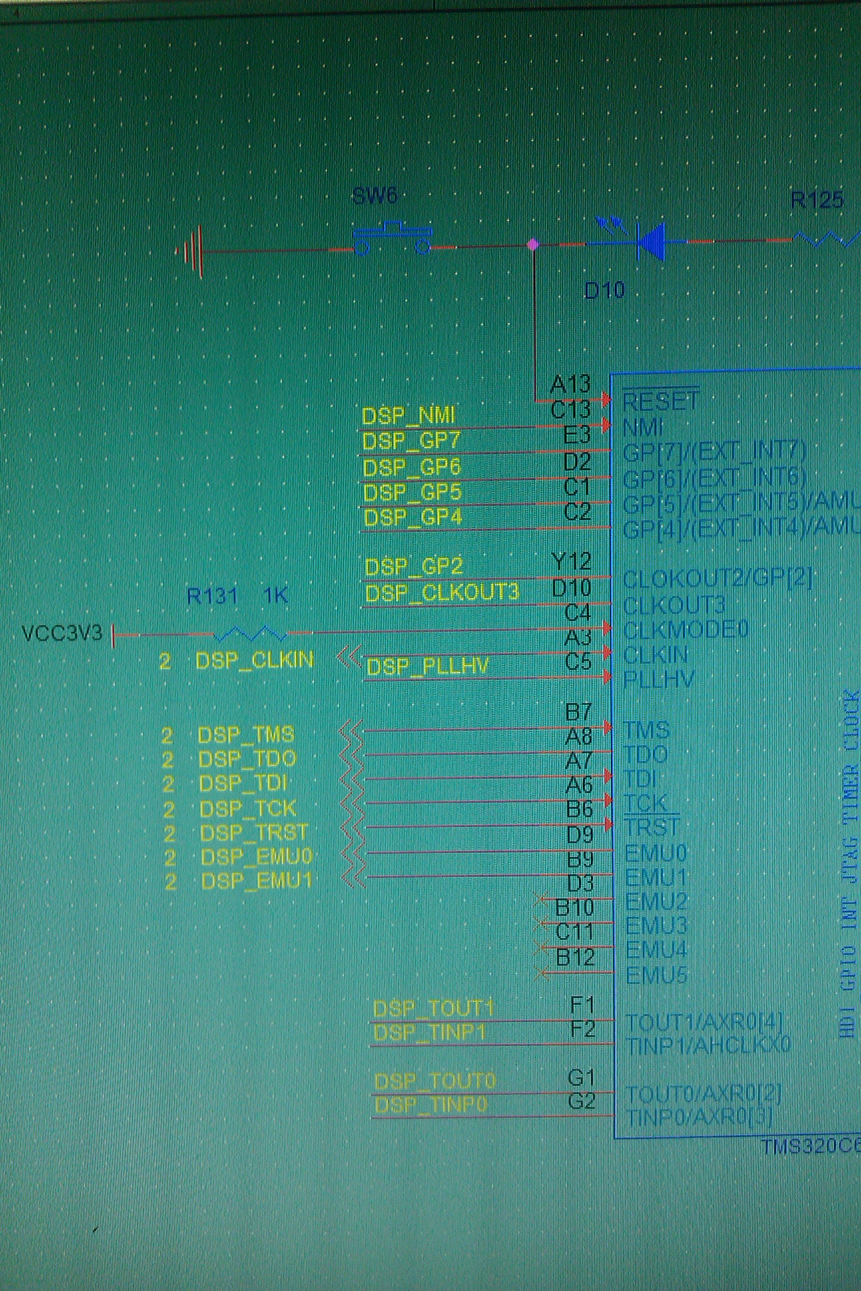
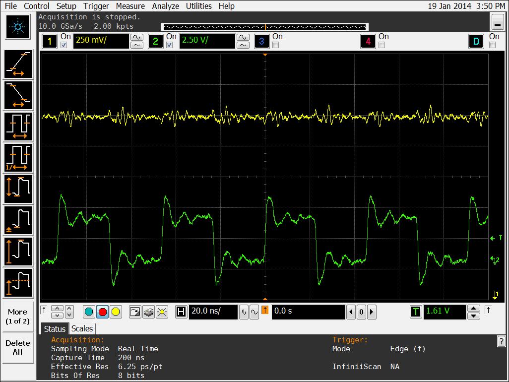
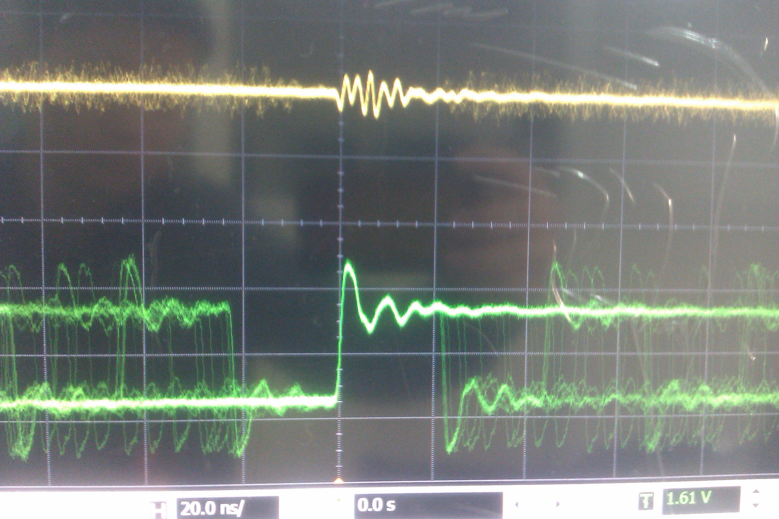
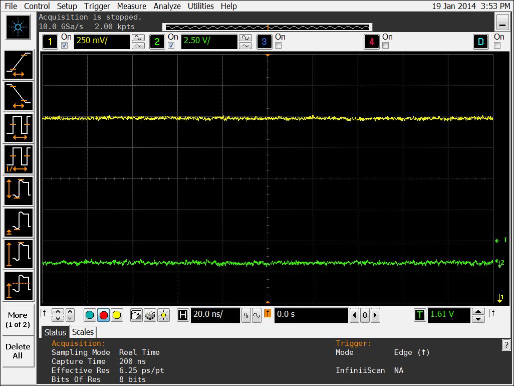
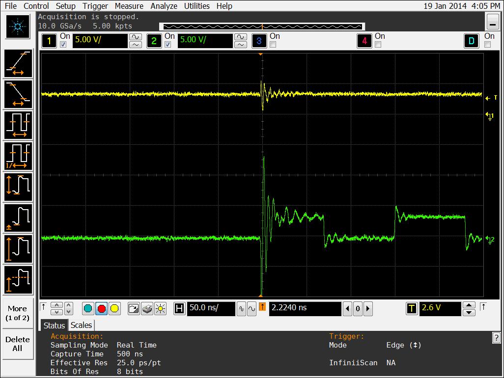
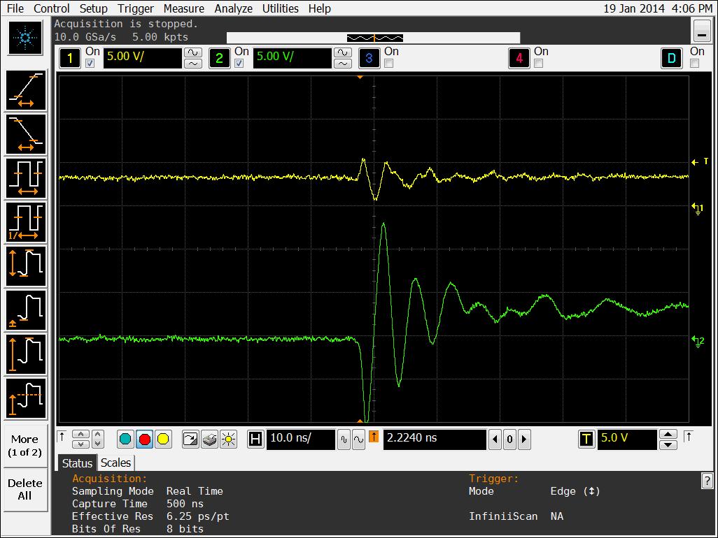
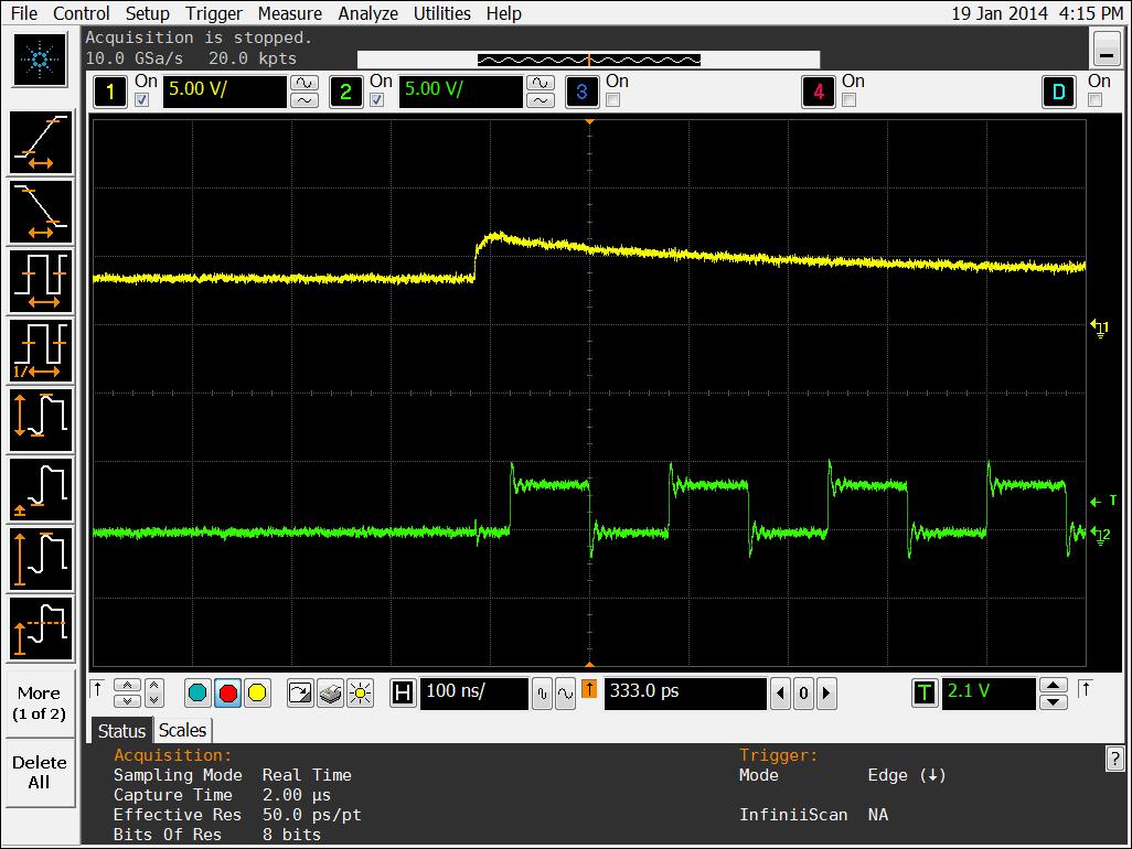
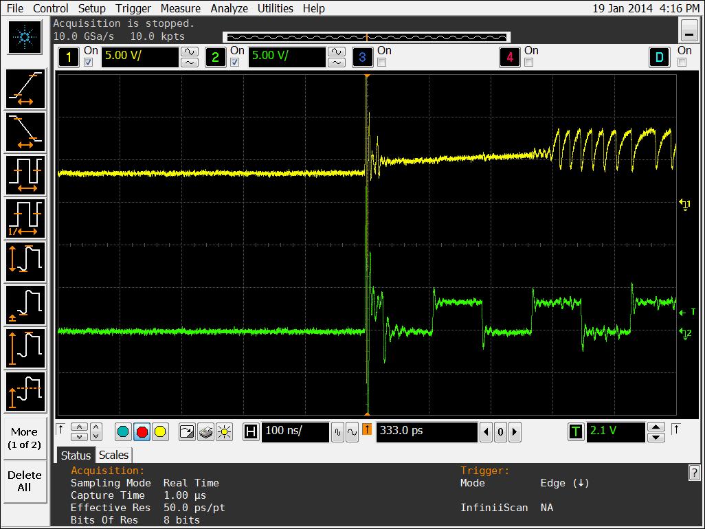
Hello, I am a beginner for dsp. In past month, I designed a dsp board. Now, I am testing the board. However, sadly, my dsp can't work. This may be the smallest thing for long time user, but I can't fing the answer. I followed the instruction on the web, and checked my clkout2 and clkout3 outputs. I found that clkout2 outputed a clock of unstable frequency before dsp was reset. After dsp was reset, clkout2 and clkout3 outputed no signal. Is my dsp IC damaged, or my circuit is wrong? Thank you very much! 

  • Yuwei Gong,

    Welcome to the TI E2E forum. I hope you will find many good answers here and in the TI.com documents and in the TI Wiki Pages. Be sure to search those for helpful information and to browse for the questions others may have asked on similar topics.

    I would be helpful to know which DSP you are using, and perhaps the location of the 'instruction on the web' that you refer to.

    There should be no time 'before dsp was reset'. When power is applied, the DSP should be held in reset until all power and clock inputs are stable. This needs to be repaired in the system design, and it may be difficult to get everything else stable before that.

    Otherwise, you are certainly on the right track by studying the clock outputs. For now, I would assume that your problem starts with power, clocks, and reset and not with a damaged IC. Of course, I cannot make that a guarantee at this point, but it is still the most likely scenario.

    Regards,
    RandyP

  • Dear RandyP:

    Thank you very much for your help, and you are very right. :)  Now I am very sure that my problem is resulted from the reset of DSP IC.

    My DSP IC is TMS320C6713BZDP-225. Its top mask is the following.

    TMS320C6713BZDP
    C20-25P01R8
    0675456               E1

    its core power is 1.2V, and  I give it the right voltage. I am in China, the location of the 'instruction on the web" is a chinese forum.

    http://bbs.ednchina.com/FORUM_POST_29_86609_0.HTM?jumpto=view_welcomead_forum_1390266273804

    The above is the link.

    Now, I think my reset circuit is defective. It generates reset signal only from a button. Reset pin remains high level when board powers on, and reset signal must be send manually.

    The above is my reset circuit, I took the picture by my cellphone, I am sorry for the inconvenience.

    The above two are the connection of configuration pins, Can you help me check them? Thank you!

    My reset circuit can not work when board powers on. The output of clkout2 is unstable after power on and before reset.the yellow one is the signal on reset pin, and green one is the output of clkout2. 

    the output of clkout2 is unstable.

    After IC is reset by button, clkout2 remains low level. PLL of DSP may not work, so the whole IC has no clock internally. I think that befor reset the dsp IC is in uncertainty. Therefore output of PLL is unstable.

    I tested my board again, and found an interesting thing. The reset signal generated by button can not work, but when I used a metal wire to touch the reset pin after button reset, to my surprise, my dsp IC were reset and worked fine. JTAG could be used too. 

    I measured the reset pin while metal wire touched the pin, and found that it produced a oscillating signal. It can reset dsp IC effectively. Then, I connected reset pin to the output of a signal generator, which produced a 3.3V pulse. I thought it should be a prefect reset signal, but it can not work too.

    In the test, I found that touching nearby ground also can reset the IC effectively.

    the yellow one shows the signal on reset pin when I touch nearby ground, and green one is the output of clkout2. Before touching PLL has no output, and after that PLL works. Therefore, dsp IC works.

    This is the enlargement of signal actions when I touch nearby ground.

    the yellow one shows the signal on reset pin when I touch reset pin, and green one is the output of clkout2. The reset signal resulted is good, and PLL works.

    In above picture, I touched the reset pin. The reset signal resulted was very bad, but it could reset dsp IC too. Then PLL worked, and the whole dsp IC worked. Can you explain it to me? Thank you!

    It is said that reset signal generated from button always has some glitches, but In above pictures reset signal resulted from touching has glitches too. however it works. can you tell me which conditions the reset signal needs to meet? or when I touched the reset pin which conditions were meet?

    I think I need a need a new reset circuit to reset IC when power on. I should use a reset IC from TI, and there should be lots of mature solutions for dsp reset. Can you give me an advice?

    Thank you very much!

    Sincerely

    Gong yuwei

  • Gong Yuwei,

    You may find some helpful articles on the TI Wiki Pages that I referenced above. Also, the DSK6713 schematics would be a useful place to start. It is very difficult to have to start your design from nothing, so we offer examples like the DSK to help you along the way; it may not be a perfect reference design but it is a good, working board.

    It looks like you have some serious board issues other than just the lack of a Power-On-Reset. Some of the noise on your traces above could just be due to your measuring equipment, but a lot of it is showing serious signal integrity issues that must be dealt with to avoid problems with your board's operation.

    You may want to check TI.com to look for a POR device. This would have the POR logic and delay, plus monitoring for handing the power-off or brown-out situation.

    Regards,
    RandyP

  • Hi, I replaced the old reset circuit with a POR IC max809. Now reset pin was hold low level when DSP powered on. The reset pin was pulled up about 250 ms after power was stable. However, DSP can not be reset too. Now I think this issue may not be resulted from reset signal.

  • Gong Yuwei,

    You have done a good job on your reset signal. This was a problem before you fixed it.

    Now you have more problems to solve. Your scope pictures show that you have a lot of noise and over/undershoot on signals. The power supplies may be very noisy. You must refer to the datasheet and the hardware design documents and normal board design methods to solve these issues. Otherwise, you will not have a reliable board design.

    Are there people at your company who can consult with you on these issues?

    Regards,
    RandyP

  • Dear RandyP:

        I am sorry, I am a student, and there is no person who can give me advice. I know that what you say is about Signal integrity, and I know its importance in PCB design. Before designing this board, I have learned SI and PI by myself for almost one year. in my board target  Impedance is controlled to be 50 OHM, and lots source Impedance matching resister are used. Unfortunately I forgot to add matching resister in the output of clkout2 and clkout3, and about 1m long probe was used in measurement. Meanwhile, the input Impedance of probe is 1M. Therefor in signal path no matching technology was used, and the scope pictures you see shows a lot of over/undershoot. Before designing PCB, I simulated the SI and PI for this board, and lots of capacitors with various value was used for power decouple.  One large value capacitor and three small value capacitors were placed near the PLLHV pin, SI and PI design may not be very good, but I think they should not be very bad too. I guess the problem may not be in this issue, but I am not sure. Do you have ever seen this problem resulted from SI or PI? what makes me most confused is that IC can be reset by touching reset pin, can you help me explain this? Thank you!

    Regards

    Gong yuwei