This thread has been locked.

If you have a related question, please click the "Ask a related question" button in the top right corner. The newly created question will be automatically linked to this question.

am335x STN LCD timing

Other Parts Discussed in Thread: AM3352

hi,TI team,

   I need to support a STN LCD with AM3352.the LCD resolution  is 320*240. 

 but the image showed in LCD is

line 239

line 0

line 1

...

line 238

I try to change the vsync timing to adjust it ,but it has no effect.  

the lcd controller register value:

Revision ............... 4f201000
Control ................ 0000bb01
Status ................. 00000000
Raster Control ......... 00080203
Raster Timing 0 ........ 01010670
Raster Timing 1 ........ 010104ef
Raster Timing 2 ........ 00000000
Subpanel Display 1 ..... 00000000
Subpanel Display 2 ..... 00000000
DMA Control ............ 00000641
Frame Buffer 0 Base .... 8e900000
Frame Buffer 0 Ceiling . 8e904b1c
Frame Buffer 1 Base .... 8e900000
Frame Buffer 1 Ceiling . 8e904b1c

the vbp  = 1,vsw = 1,vfp = 1

  • From your setting it looks like this is an 8bpp mono STN display. Have you defined a palette in the frame buffer? Please check the AM335X TRM Rev. J, sections 13.3.5 for details.
  • hi,biser,

        it's 1BPP mono display ,and 8-bit  output data bus. it's with 32 bytes palette buffer.the palette entry 0 is 0x00, and the palette entry 1 is 0xFF.is it right?

  • For 1bpp mono the framebuffer size should be (320*240)/8+32=9632 bytes or 0x25A0. You have set the framebuffer to 0x4B1C or 19228 bytes. See Table 13-9 in the AM335X TRM, Rev. J. Moreover your two framebuffers overlap. For pallete size 32 bytes is correct, for format see Figure 13-6.
  • Also check these notes below Figure 13-5:
     
    •  Each entry in a palette occupies 2 bytes. As a result, 8-BPP mode palette has 256 color entries while the other
       palettes have up to 16 color entries.
    • 4-BPP mode uses up the all the 16 entries in a palette.
    • 1-BPP mode uses the first 2 entries in a palette while 2-BPP mode uses the first 4 entries. The remaining entries
       are not used and must be filled with 0.

  • hi,biser,

           I check the  the palette buffer again and I think it's ok.

          I think maybe the hsync signal and vsync signal timing are not match the lcd requirement.


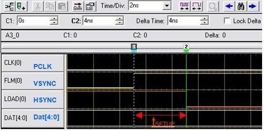
    tsetup = 4ns (Can’t meet STN Spec. tsetup>100ns)

    How to change the hsync and vsync timing to be consistent with LCD's spec?

  • I neither know the LCD type, nor do I have the LCD spec. How can I say? Can you post the datasheet?
  • hi,biser,

        We also have no the datasheet on hand.And we only have the timing chart of the LCD.

        The following chart is the STN timing of another CPU LCD controller.

    the VFRAME is the VSYNC signal,and the VLINE is the HSYNC signal.The WDLY is what we want.How to add the delay time from the last hsync falling edge to the vsync rising edge?

    we think the STN LCD maybe shifted the last line data to the first line of the next frame because the last hsync falling edge and the vsync rising edge are nearly generated at the same time in AM335X.

  • These are the horisontal front anf back porch times (HFP and HBP). Looks like they have to be equal in your case. Register RASTER_TIMING_0 holds the lower 8 bits (bits 7-0) of these times (Bits 31-24 for HBP and bits 23-16 for HFP). Register RASTER_TIMING_2 holds the higher 2 bits (bits 9-8) of these times (Bits 5-4 for HBP and bits 1-0 for HFP). The total 10-bit value (from 1 to 1024) specifies:
     
    For HBP: the number of pixel clock periods to add to the beginning of a line transmission before the first set of pixels is output to the display (programmed value plus 1).
     
    For HFP: the number of pixel clock periods to add to the end of a line transmission before line clock is asserted (programmed value plus 1).