


Hi Folks,
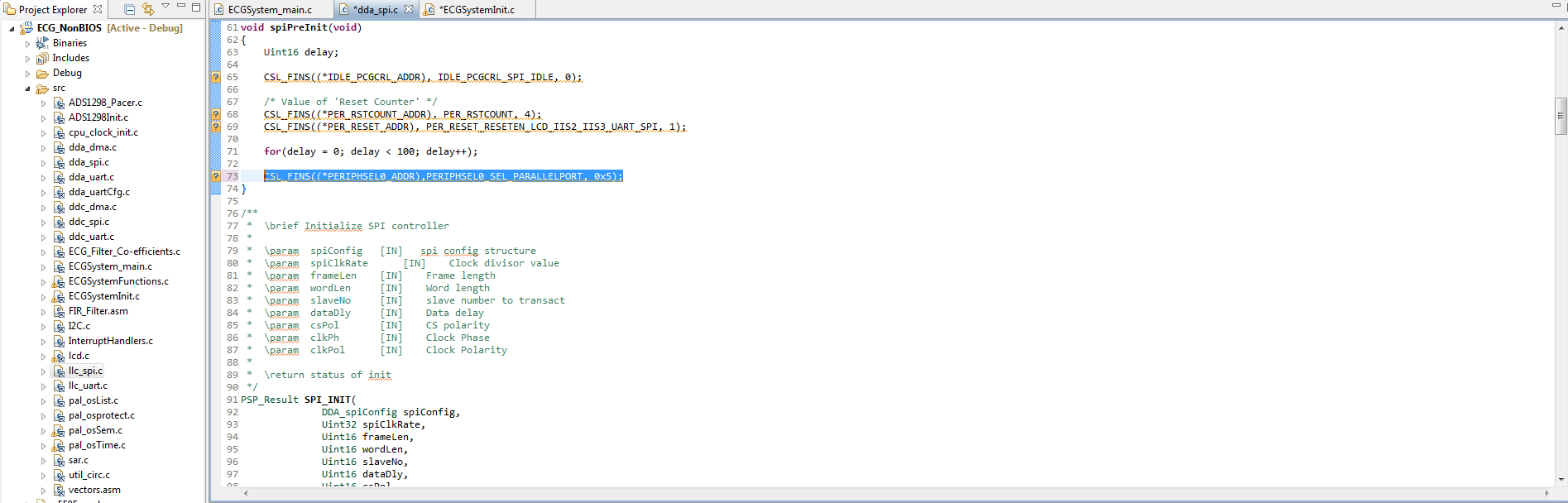
We have a crucial problem. We are working on the original ECG code provided by TI (http://c5505-ezdsp.googlecode.com/files/ADS1298_ECGSystem_C5515EVM.zip) . This code uses PPMode=5 which includes UART and LCD to show ECG signal. However, this mode does not include the other SPI CS, only SPI CS0.
We desire to run this code by using SPI CS1.
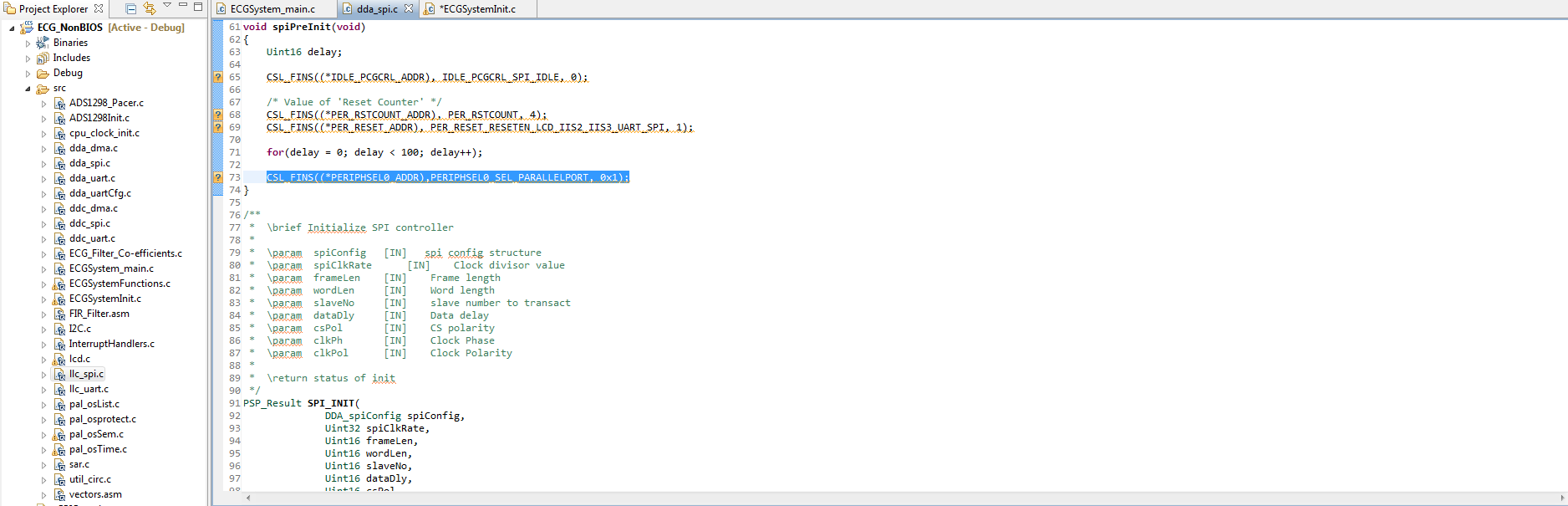
Because pin multiplexing is necessary, we firstly changed PPMode from 5 to 1 which supports SPI CS1. Another reason of selecting PPMode=1, this mode also supports UART. So, if we run the code successfully, we can observe the ECG signal on computer by using C55x ECG ADS1298 Medical Development Kit (MDK).exe.
PPMode=5;
PPMode=1;
Then, we change the slaveNo in order to select chip select no. We changed chip select no from 0 to 1. These modificiations which we made are related to code.
CS=0;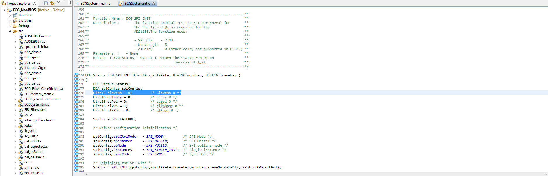
CS=1;
On the other hand, we changed some pin and jumper configuration. Before the modification, CS0 on EVM (J13–7th pin) are connected to ADS1298 CS pin (JP21–2nd pin) with a jumper between JP21–1st pin and JP21–2nd pin. In order to select CS1, we removed jumper and we connected CS1 on EVM (P1–14th pin) to ADS1298 CS pin (JP21–2nd pin).
The result of all above modifications is that we could not run the code via CS1.
On the oscilloscope, when CS0 selected, we observe that 8kHz pulses, however; we observe that 250Hz pulses when CS1 selected.
What can be the problem with the modified code or modified configuration?
Regards,
Burak