This thread has been locked.

If you have a related question, please click the "Ask a related question" button in the top right corner. The newly created question will be automatically linked to this question.

Booting DSP of OMAPL138 from ARM(without OS)

Other Parts Discussed in Thread: OMAPL138, OMAP-L138

Hello,

I am trying to boot DSP of OMAPL138 via ARM. In ARM I have used normal C code. [Both DSP & ARM - NON OS mode].

I am using calixto's OMAPL138 custom board for this purpose.

With reference to discussion on few e2e links I can understand:

1.  We can boot DSP using AISGEN tool and sfh utility.

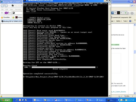
       I tried this technique, with proper PSC, PLL configuration in required tab of AISgen tool. Created one ARM bootable binary, then with the help of out2rprc tool merged the application and boot image to single .bin . And then used normal SFH command to load merged file(outcome of out2rprc) and boot file(outcome of AISgen) to NAND of omapl138. Here I am getting BOOTM properly, but control comes to line "Waiting for SFT on OMAPL138" and waits here only. To resolve this issue, i took help from  already existing e2e posts on the same issue and as suggested there I used latest ubl & uboot files from calixto and follwed the procedure, but still the problem persists!!!!!!


2. In 2nd method, I am using pure C code from ARM to wake up DSP by putting entry point(1k aligned) in HOST1CFG register and all required programming of PTSTAT,MDSTAT registers. Here I am giving .out file of my DSP to ARM code as input. From code dubugg, i can see that ARM code is exracting entry point of DSP code correctly, its waking up DSP but control doesn't go to DSP, its stays in ARM code only giving warning as "c_init00: has seletal debug info only".

Please provide the solution to this problem ASAP.


  • Hi Prajakta,

    i am suggesting that to do some exercise on OMAPL138EVM to run ARM-DSP-LED program which is using ARM UBL to wake up the DSP and running the DSP's LED out file(c_init00) by flashing ARM-DSP-LED binary into external memory(NAND, SPI)  through serial flasher utility.

    then you will get better clarity about boot sequences of OMAPL138 (Running DSP binaries after ARM UBL) and modify your code and test it.

    Please refer below TI wiki for loading DSP binary with ARM UBL.

    http://processors.wiki.ti.com/index.php/Boot_Images_for_OMAP-L138

    Coming to the first point,

    Hanging at  "Waiting for SFT on OMAPL138"

    Q1) What commands have you followed to flash AIS formatted binaries(which is combined AIS formatted binary of ARM UBL & DSP out file) into NAND flash?


    Example for loading combined AIS formatted binary of ARM UBL & DSP out file into NAND Flash through serial flasher utility:

    ..\sfh_OMAP-L138.exe -flash_noubl ARM-DSP-LED.ais -flashType NAND -targetType OMAPL138


    Still the problem continues then provide  "OMAPL138_LCDK"   as a targetType in serial flash utility.


    Note:

    1) You can chnage the flash type & target type as per your requirement.

    2) If you are not mentioned anything like this then default config get enabled (targetType is OMAPL138 & flashType is SPI_MEM)

    To know more about serial flasher utility, please follow the below TI wiki

    http://processors.wiki.ti.com/index.php/Serial_Boot_and_Flash_Loading_Utility_for_OMAP-L138


    In 2nd method, I am using pure C code from ARM

    Q2) Is this 'C' code is provided by TI or yours?

    I will come back to you later for the 2nd point.

    mean while please follow the above said TI wikis & procedures and let me know.

  • Hi,

    For 1st point:

    Yes I am using same sfh command. Even i tried giving ARM bootable and application binary(dsp bin file) with command:

    ..\sfh_OMAP-L138.exe -flash  -flashType NAND -targetType OMAPL138 -p COM1 ARM.ais DSP.bin

    But still no use!! Booting again stucks at "Waiting for SFT on OMAPL138...." line. 


    For 2nd point:

    I used my C snippet. For that I refered, point 13.2 of SPRUH77(technical Refernce Manual of OMAPL138) to wake up DSP. And before waking up DSP I put ARM in supervisory mode.( For this i refered startware provided by TI).

    Waiting for reply...

    And meanwhile I 'll surely try that  LED code available on TI site, but as I can see it will require some changes as per my custom board. Will do it and come back to you. THANKS..

  • Hi,

    For 2nd point:

    I used my C snippet. For that I refered, point 13.2 of SPRUH77(technical Refernce Manual of OMAPL138) to wake up DSP. And before waking up DSP I put ARM in supervisory mode.( For this i refered startware provided by TI).

    So, You have created new CCS project yourself with linker command file,

    If it so, It might have problem with CCS configurations, then take DSP LED program's CCS project & remove LED  blinking stuffs code and add your code & built it (with proper linking & boot.asm )

    Coming to the 1st point,

    Change  your command or flashing

    from

    ..\sfh_OMAP-L138.exe -flash  -flashType NAND -targetType OMAPL138 -p COM1 ARM.ais DSP.bin

    to

    ..\sfh_OMAP-L138.exe -flash_noubl  ARM-DSP-combined.ais  -flashType NAND -targetType OMAPL138_LCDK -p COM1

    Note:

    Combine your ARM + DSP (add ARM first and DSP as second) program (.out)  by AISGen tool with as per your .cfg (custom board) file

  • Hi Prajakta Ranade,

    First Method:[SFH]

    The following might also be the reasons for getting or hanging at  "Waiting for SFT on OMAPL138".

    1. If the flash device is not available or not enabled to access. I mean to say, if you use NAND flash, make sure that the device is available for SFT to flash the image. To confirm this, you can give erase command and check using sfh utility.

    "sfh_OMAP-L138.exe -erase -targetType OMAPL138_LCDK -flashType NAND -p COM1"

    The sfh utility will not check the availability of flash memories on board and doesnot throw any error if not available.

    Case A: If erase is not successful, please check in either your custom-boot-load source code and *.cfg file enabled the flash memory used. ( i.e., in this case NAND) and the configurations like flash width and timing respectively. 

    Excerpt from .cfg :

    Boot Mode=(No Config)

    Boot Speed=115200

    Flash Width=0

    Flash Timing=3ffffffc

    Case B: If erase is succesful, please follow the procedure below to narrow down the problem.

    2. If the target type( -targetType)  specified doesnot match. (or any of the arguments to the sfh is not right).

    3. The sfh utility need modifications in case of custom board. It will work straight away only with TI EVMS/LCDK. For more info about modifications please visit the below wiki and do the necessary changes in the source code of sfh utility to make it work with your custom board.

    http://processors.wiki.ti.com/index.php/Serial_Boot_and_Flash_Loading_Utility_for_OMAP-L138#Modifications_for_Custom_Boards

    ---------------------------------------------------------------------------------------------------------------------------------------------

    Procedure:

    1. Using CCS, create the ARM boot binary and generate *.out ( let us say this as ARMOUT.out)

    2. Using CCS, create the DSP application binary and generate *.out ( let us say this as DSPOUT.out)

    3. This is how you have to combine the two binaries:- Execute AISGEN tool and feed the appropriate *.cfg file by clicking "File-->Load configuration-->select *.cfg".  In the column of "ARM application file", select your  ARMOUT.out and using "+" option select your DSPOUT.out.

    4. Generate the AIS Output file by giving the output path and the name of the output binary ( let us say as ARMOUT_AND_DSPOUT.out.ais)

    5. Connect the target to the host PC through serial port and do the serial port configuration ( 8N1, 115200, Flowcontrol - NONE)

    6. Check the "BOOTME" message is received on your serial output terminal and close the terminal.

    7. Being in Command line, using sfh, give erase command which erases the flash.( This step will ensure that the flash is available for access).  

    "sfh_OMAP-L138.exe -erase -targetType OMAPL138_LCDK -flashType NAND -p COM1"

    8.  If step 7 is successful, then the flash command below should work without any problem.

    "sfh_OMAP-L138.exe -flash_noubl ARMOUT_AND_DSPOUT.out.ais -targetType OMAPL138_LCDK -flashType NAND -p COM1"

    or

    "sfh_OMAP-L138.exe -flash_noubl ARMOUT_AND_DSPOUT.out.ais -targetType OMAPL138 -flashType NAND -p COM1"

    ( -- Even in our OMAPL138 SDI EVM, it accepts the -targetType as "OMAPL138_LCDK" instead of "OMAPL138", though it is not a LCDK. Please do check for your custom board. Give it a try with "OMAPL138_LCDK")

    9. If the 7th step is not successful, follow "Case A" given above.

    10. If 8th step is not successful, it might be someother problem. If this is the case, please share your ARM code, DSP app code, Gel file, *.cfg, linker.cmd and your CCS project files; So that we will reproduce your issue and try to resolve it.

    Second Method:[CCS]

    In CCS, while loading the ARM (UBL? ) code and DSP application binary, after the ARM UBL runs, whether the "connect target step" for DSP core is done??  by which the DSP wake up gets completed and then the DSP binary should get loaded using load options: Run->Load->Load Program -->select DSP-application.out (Did you do this?)

    Other useful links:

    1. CCS gel file to debug the boot issue: http://processors.wiki.ti.com/index.php/OMAP-L1x_Debug_Gel_Files

    2. List of things to be noted while booting DSP binary: http://processors.wiki.ti.com/index.php/Boot_Images_for_OMAP-L138#Booting_DSP_Binaries

    Regards,

    Shankari

    -------------------------------------------------------------------------------------------------------

    Please click the Verify Answer button on this post if it answers your question.
    --------------------------------------------------------------------------------------------------------

  • Hi Shankari,

    Thanks for reply.

    While i try to run board using point 1 mentioned by you, some issues for point 2.

    Here I am using normal C code in ARM, so it generates .out file in CCS. When i load this .out file in CCS, how can I reload DSP .out file??

    For reference my ARM code is:

    void main(void)

    {

    _call_swi(327680); //Put ARM in previledge mode

    // Do all PSC & PLL configuration with KICK registers unlicked.

    //feed entry point of DSP's c_init00 (please note that I am giving address, which is already aligned to 1K in .cmd of DSP project)

    entry_point=0x11804c00;

    SYS_REGS->HOST1CFG = entry_point;

    //Wake up the DSP

    CSL_FINST(psc0Regs->MDCTL[CSL_PSC_DSP], PSC_MDCTL_NEXT, ENABLE);

    CSL_FINST(psc0Regs->PTCMD, PSC_PTCMD_GO1, SET);

    while(CSL_FEXT(psc0Regs->PTSTAT, PSC_PTSTAT_GOSTAT1==CSL_PSC_PTSTAT_GOSTAT1_IN_TRANSITION);

    CSL_FINST(psc0Regs->MDCTL[CSL_PSC_DSP], PSC_MDCTL_LRST, DEASSERT);

    //inserting some delay of almost 5secs

    while(1);

    }

    Now, in first stage of coding, I tried blinking a LED from ARM side with proper gpio configuration and it works file. So ARM is running its code properly at it's end.

    But when I insert, my DSP.out file ,

    It gives me error as : File DSP.out dose not match target type , not loaded.

    And in debug window, am getting warning as: _c_init00 has skeletal debug info only.

    If, i run only DSP code its working properly.

    So can you please elaborate how to use these both ARM.out & DSP.out files from CCS to load them in board.


  • Hi Prajakta,

    Using your DSP entry point and your ARM code, my DSP app. works perfectly.

    I Commented out only the "_call_swi" function in your ARM code & used KICK registers since i'm using 'boot.asm' file for putting ARM in privilege mode & Using KICK registers for accessing SYSFG & HOST1CFG registers in my CCS project.

    Please find the attached of the CCS source code project for the same.

    6330.OMAPL138-ARMUBL-DSPLED_work.zip

    Note: I have followed the 1st method to flash the combined ARM UBl & DSP LED app into SPI flash.

    Please answer the following questions to help you further,

    1) Have you tried the 1st method which Sknakari suggested in the previous post? If it yes, How does it goes? & What is the actual result? If not, What are the challenges you faced in not doing so ?

    2) Did you modify the "sfh" for your custom board as per this link? ( as Shankari suggested)

    3) Did you confirm that the NAND flash device is available to do the 'erase' operation first before flashing?

    4) Is it possible to share all the Source code ( ARM code, DSP app, .gel, .cmd, .cfg) to us through private conversation?

      If it so, It might have problem with CCS configurations, then take DSP LED program's CCS project & remove LED  blinking stuffs code and add your code & built it (with proper linking & boot.asm )

    Have you followed this step which i gave in previous reply ?

    If not, Please follow it & let me the know the result.

  • Hi Titusrathinaraj,

    Thanks a lot for quick reply.

    As mentioned by Sknakari, I tried erase command, and it seems my NAND is not accessible to me!! As I am still getting waiting for SFT...

    So I am working on that issue simultaneous. Will come to you on this issue in couple of days, as I need to look into my hardware & source code to make required changes.

    Now on CCS part:

    As per your previous reply, I tried importing example code for blinking LED in my workspace, but its showing me  error as " compiler definition not available "  It needs ARMv5.0 & C6000v7.4 compilers, i guess. Even I tried importing exaple posted by you in zip file, still same error!!!

    As I mentioned in my previous reply, while running these two code simultaneously I am getting error message. I went throught ti wikis on multicore processing ets. but none of those are telking about booting sequence/steps to be followed in CCS!!!!

    So,can you please tell me, how to exactly run these two projects on CCS. [I am using CCSv5.2 version]. [Detailed steps would be preferable]

    I can share complete code for DSP & ARM with you. Please tell me how to share these projects on personal conversation.


  • Hi Prajakta,

    Prajakta says said:
    As per your previous reply, I tried importing example code for blinking LED in my workspace, but its showing me  error as " compiler definition not available "  It needs ARMv5.0 & C6000v7.4 compilers, i guess. Even I tried importing exaple posted by you in zip file, still same error!!!

    Follow the procedures from the below link to import CCS project.

    http://processors.wiki.ti.com/index.php/Importing_Projects_into_CCS http://processors.wiki.ti.com/index.php/Projects_and_Build_Handbook_for_CCS

    Use the below TI processors wiki link and TI website to search all kind of TI documents (CCS, gel file, linker command, technical note etc.,)

    http://processors.wiki.ti.com/index.php/Main_Page

    www.ti.com

    You can send your source code to Shankari through Mr.Hemraj.

  • Hi Prajakta,

    We received your source code and thanks for the update that the "SFT hang issue" gets resolved by modifying SFT source.

    I have ensured that your DSP app ( the source code which you sent) gets waken up successfully through your ARM code.
    I have confirmed this by just introducing a led blink in your main function of dsp app. Please refer to the modifed source code sent via Hemraj.


    To flash the combined images into SPI memory, use the command as below.

    ./sfh_OMAP-L138.exe -flash_noubl <The combined ARMUBL and DSP app through AISGEN tool> -flashType SPI_MEM -targetType OMAPL138

    for e.g., for SPI
    ./sfh_OMAP-L138.exe -flash_noubl Combined-ARMRBL-CG_DSPAPPout.ais -flashType SPI_MEM -targetType OMAPL138

    for e.g., for NAND
    ./sfh_OMAP-L138.exe -flash_noubl Combined-ARMRBL-CG_DSPAPPout.ais -flashType NAND -targetType OMAPL138


    I have noticed a "Read error" in the screenshot sent through Hemraj while your flashing ARM & DSP app code into NAND flash.

    As already communicated with you, before flashing code into NAND flash, please confirm that the NAND flash device is available to do the 'erase' operation.

    "sfh_OMAP-L138.exe -erase -targetType OMAPL138_LCDK -flashType NAND -p COM1"

    What are all the modifications have you made in hardware and software related to NAND configurations?

    What about NAND bus width (8 bit or 16 bit) configuration?

    What chip select has been used for NAND flash?

    Please change the NAND BUS width in below file & compile your SFT source code.

    OMAP-L138_FlashAndBootUtils_2_40/OMAP-L138/Common/include/device_async_mem.h

  • Hi Titusrathinaraj,

    Thanks a lot for your quick response.

    A]

    About source code that i have sent: It is working fine at my end only if I mentioned boot mode as UART2 in AISgen utility while combinig my ARM.out & DSP.out files and producing ARM_DSP.ais. And i am running it using UARThost utility.

    If I configure boot mode as NAND with proper boot selctiion pin setting in hardware, its not running. [Niether by UARThost utility nor by SFH]

    B]

    As you suggested previously, i have already tried erasing NAND using above mentioned command, and its getting erased. I am attaching screen shot of the same for reference.

    Also, I checked for:

    NAND bus width (8 bit or 16 bit) configuration = 8bit

    chip select has been used for NAND flash = CS3

    And have already done in OMAP-L138_FlashAndBootUtils_2_40/OMAP-L138/Common/include/device_async_mem.h. & device_nand.h files.

  • Hi,

    1) Please run starter ware sample NAND application in your board to ensure/test the NAND functionality of your board (hw &  s/w)

    OMAPL138_StarterWare_1_10_03_03/examples/evmOMAPL138/nand/nandReadWrite.c

    2) Please refer the below TI wiki to calculate the NAND timing parameters for CEnCFG register of EMIFA.

    Refer the chapter 20.4.5 of OMAPL138 TRM.

    http://processors.wiki.ti.com/index.php/Programming_Asynchronous_EMIF_on_OMAP-L13x_/_C674x_/_AM1x