This thread has been locked.

If you have a related question, please click the "Ask a related question" button in the top right corner. The newly created question will be automatically linked to this question.

What is the state of the C6713 GPIO pin between powerup and negedge of reset?

I would like to confirm what state of the 6713 GPIO between powerup and negedge of reset.

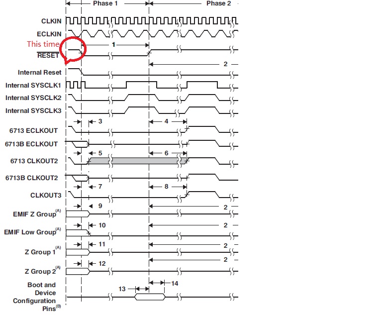
According to Reset Timing of Data manual, Notes B(Boot and Device Configuration Pins),The state of these pins  is Tri-State, others  is Uncertain state at these time. Is Understanding OK ?

Can someone tell me what state of two group GPIO between powerup and negedge of reset, tri-state/input /output or uncertain state?  Thank you very much!


  • Hi ,

     At reset, GPIO output pins default to the value in the GPIO value register (GPVAL). If it is necessary to drive the GPIO output to the high-impedance state, the GPIO pins can be configured as an input pin and then changed to an output pin.

    Please refer SPRU584A General-purpose Input/output reference guide page no 29 for more details.

    To ensure a proper logic level during reset, it is recommended to include an external 10 KOhm Pullup/Pulldown resistor to sustain the IPU/IPD respectively

    Regards

    Antony

    • --------------------------------------------------------------------------------------------------------
      Please click the Verify Answer button on this post if it answers your question.
      --------------------------------------------------------------------------------------------------------
  • Thank you for your reply!

    but i want to know GPIO state before  reset  after poweron ,not during reset.

     Although there are pull-down resistor,i am not sure the state during that time. Could you tell me? Thanks!

  • Hi,

    Before reset after power on, that is Power-On-Reset (POR). Explicitly mentioned in the C6713 datasheet SPRS586F section 5.4.1 Power-On-Reset (POR).

    POR sets all of the device internal logic to its default state. All pins are tri-stated with the exception of RESETOUT which remains active through the reset sequence.

    Hope this statement clears your clarification.

    Regards

    Antony

    • --------------------------------------------------------------------------------------------------------
      Please click the Verify Answer button on this post if it answers your question.
      --------------------------------------------------------------------------------------------------------
  • thank you!

    but I would like to confirm what state of the 6713 GPIO between powerup and negedge of reset,that is before POR. that is to say what are the pins  before negedge of reset,ti-stated/input/output or uncertain?  

  • SFloat,

    Please refer to the C6713B datasheet's section on Reset. This is at the bottom of page 98 in SPRS294B.

    SPRS294B 'reset' said:

    A hardware reset (RESET) is required to place the DSP into a known good state out of power−up.

    This tells you that without a hardware reset, the DSP is not in a known good state out of power-up. So without the negative edge of RESET, no outputs can be considered to be at a known state. This means they will all be at an uncertain state, to use your terms.

    SPRS294B 'reset' said:

    As a best practice, reset should be held low during power−up.

    We have become more clear about this with more recent DSPs, and tell you that RESET must be held low during power-up to prevent damage to the device. The C6713B does not have the problem with damage under these circumstances, but there is no way to predict the value at any output or any internal state before RESET has been pulled low.

    If you follow the best practice as stated in the datasheet, you will have all of the GPIO outputs at the initial states as described in the datasheet. Some GPIOs may have internal pull-ups and some may have internal pull-downs. Depending on your bootmode and other configuration settings, the datasheet explains the initial states of all the pins. If there is a particular pin in a particular mode that you do not understand the datasheet's description for, please let us know.

    Regards,
    RandyP

  • Thank you very much for your answer!

    I will pay attention to this problem in the following design.