


Hi,
I have a custom board with a C6746 DSP (375MHz) + DDR2-800 128MB (W9712G6JB-25 from Winbond) and I can't get the DDR2 to work. I don't have a JTAG or any other emulation option available, only a single LED connected to a GPIO port in C6746.
To configure the DDR2, I used AISgen with this configuration:
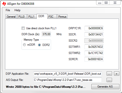
The register values were taken from the spreadsheet given here:
http://processors.wiki.ti.com/index.php/Programming_mDDR/DDR2_EMIF_on_OMAP-L1x/C674x
The timing values were taken from the DDR2 manual (page 45/46)
In my project, in the .cmd file, the DDR2 config is:
DDR2 o = 0xC0000000 l = 0x08000000 /* 128MB DDR2 Data */
SECTIONS
{
.ddr > DDR2
...
}
And, in my main.c, I declared a buffer in the external memory:
#pragma DATA_SECTION (ddr_buff,".ddr");
volatile char ddr_buff[ACNT_RX*BCNT_RX*CCNT_RX];
And then I do a write and read. If the bit is 1, the LED (connected to my GPIO) turn on, else, turn off. Shift right and repeat:
for (i = 0; i < ACNT_RX*BCNT_RX*CCNT_RX; i++)
ddr_buff[i] = 0x55;
while (1)
{
pattern = ddr_buff[0];
for (i = 0; i < 8; i++)
{
if (pattern & 0x01)
*((int *)0x01E26040) = 0x00000001; //LED ON
else
*((int *)0x01E26044) = 0x00000001; //LED OFF
for (pattern2 = 0; pattern2 < 0x100; pattern2++);
pattern = pattern >> 1;
}
I don't see the same word I wrote in the oscilloscope, so I'm assuming my DDR write/read is not working, therefore, the boot was not ok.
Am I doing something terribly wrong, missing something or I may consider a hardware problem (schematic/layout/solding)?. I'm rather new to this, so I don't exactly know how to procede here.
Thank you in advance.
Best Regards,
Leonardo Trierveiler
