This thread has been locked.

If you have a related question, please click the "Ask a related question" button in the top right corner. The newly created question will be automatically linked to this question.

Booting Via Spi Or Uart on 6747

Other Parts Discussed in Thread: OMAP-L137, CCSTUDIO

I have a simple memory test program that blinks some leds. I want to be able to boot into this program via spi flash on SPI1 and/or the uart.

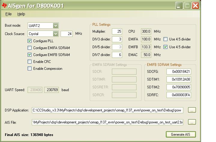
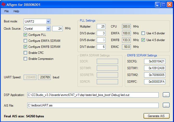
I converted my .out file to a .bin file using the aisGen utility. I programmed the spi flash and set the config bits appropriately and when I reset the board I see data coming out of the spi flash but the chip does not boot. (No leds and no sdram access)  I thought it is probably something in my code that I did not include form the Gel file.

That is when I tried  programming via the uart. I changed the config pins and hooked up a rs232- 3.3Vttl adapter. I can see "bootme" using putty so I think the chip is configured correctly.  I closed putty and opened the "Uart boot host" utility from TI. When I start the program then reset the board here is what I get.


(File IO): Read 31080 bytes from file C:\Documents and Settings\ldavis\Desktop\sdram.bin.
(Serial Port): Opening COM3 at 230400 baud...
(AIS Parse): Read magic word 0x41504954.
(AIS Parse): Waiting for BOOTME...
(AIS Parse): Performing Start-Word Sync...
(AIS Parse): Performing Ping Opcode Sync...
(AIS Parse): Processing command 0: 0x58535963.
(AIS Parse): Performing Opcode Sync...
(AIS Parse): No slave memory present; Sequential Read Enable has no effect.
(AIS Parse): Processing command 1: 0x5853590D.
(AIS Parse): Performing Opcode Sync...
(AIS Parse): Executing function...
(AIS Parse): Processing command 2: 0x5853590D.
(AIS Parse): Performing Opcode Sync...
(Serial Port): Read error! (The operation has timed out.)
(AIS Parse): I/O Error in read!
(Serial Port): Read error! (The operation has timed out.)
(AIS Parse): I/O Error in read!
(Serial Port): Read error! (The operation has timed out.)
(AIS Parse): I/O Error in read!
(Serial Port): Read error! (The operation has timed out.)
(AIS Parse): I/O Error in read!
(Serial Port): Read error! (The operation has timed out.)
(AIS Parse): I/O Error in read!
(Serial Port): Read error! (The operation has timed out.)
(AIS Parse): I/O Error in read!
(Serial Port): Read error! (The operation has timed out.)
(AIS Parse): I/O Error in read!
(Serial Port): Read error! (The operation has timed out.)
(AIS Parse): I/O Error in read!
(Serial Port): Read error! (The operation has timed out.)
(AIS Parse): I/O Error in read!
(Serial Port): Read error! (The operation has timed out.)
(AIS Parse): I/O Error in read!
(Serial Port): Read error! (The operation has timed out.)
(AIS Parse): I/O Error in read!
(AIS Parse): Opcode Sync failed after 11 consecutive I/O failures.
(AIS Parse): Boot aborted.
(Serial Port): Closing COM3.


So it looks like it starts doing something, then freaks out. Any thoughts on what would cause this?

Thanks

Ringo


  • I also got our 6747 EVM board and tried to program that via Uart2. I get exactly the same results. It sees the bootme, but then gives the same errors. I reviewed the EVM docs and verified the boot dip switched are in the correct place, I don’t think I would get bootme if they were not. The EVM has a 24.000Mhz clock on it. My board has a 24.576 clock so I thought maybe that was the problem on my board but then the EVM should have worked.


    Could bad code cause the bootloader to fail like it is?  Is there  a .bin file for me that will work on the EVM, just to rule out that it is my code. Just something to blink and led or something will be enough to see if it is my code causing an error or not.


    Is there anything else that needs to be set up other than the boot cfg pins that I could have missed?


    Ringo

  • Ringo,

    I just tried the UART2 boot on my L-137 EVM and get a similar failure.  My program actually gets a little farther but still gets the I/O read error and I have to abort the boot.

    Are you still having problems with this?

    I have a similar question for TI support.  I have a custom target that has a 19.2 MHz clock input (NOT 24 MHz).  Is it still possible to do a UART boot?  In other words, how can we adjust the baud to match the speed of our input oscillator?

    This Wiki page talks more about serial boot and also mentions the problem of using a custom board w/o a 24 MHz clock but doesn't give a solution:

    http://wiki.davincidsp.com/index.php/Serial_Boot_and_Flash_Loading_Utility_for_OMAP-L137

    Note that is also mentions to use Windows HyperTerminal as the terminal emulator but this application does not go up to the required 230400 baud.

    Has anyone verified that it is possible to use the UART Boot Host application to do a successful boot of the L-137 EVM?

    thanks,

    Mike

  • My problem was user error. I had built the file for Spi boot and never changed it for uart boot.

    I am using a 24.576Mhz clock with no issues.

    Ringo


  • Ringo,

    Quick question to maybe help me.  Are you able to use a normal RS-232 connection with your PC?  I'm finding that 230400 seems too fast for the com port on my PC.  I had to use a USB - RS232 device and have the USB act like a COM port.  Also, the driver properties only seem to go 115200 so I'm not sure I can get a connection upto 230400.


    Mike

  • I don't know if anyone has tried a PC serial port, we generally use a USB-ttl converter. The one I use has and FTDI 232R chip on it.

    We have been able to connect at 23400 with Hyperterm and putty. I thought that hyperterm only went to 115200,  but that may be on native ports, with this adapter I get a couple options above even 230400.

    Ringo


  • Ringo,

    I still can't get mine to work.  Can you verify that we are using the same applications:

    AISgen for D800K001 version: 0.9.0.0

    UART Boot Host version: v1.0

    Here is a screenshot of generating the AIS binary:


    Here is a dump of output from UART Boot Host:

    (File IO): Read 136940 bytes from file C:\CCStudio_v3.3\MyProjects\dsp\development_projects\omap_l137_evm\power_on_test\Debug\power_on_test_uart2.bin.
    (Serial Port): Opening COM3 at 230400 baud...
    (AIS Parse): Read magic word 0x41504954.
    (AIS Parse): Waiting for BOOTME...
    (AIS Parse): Performing Start-Word Sync...
    (AIS Parse): Performing Ping Opcode Sync...
    (AIS Parse): Processing command 0: 0x5853590D.
    (AIS Parse): Performing Opcode Sync...
    (AIS Parse): Executing function...
    (AIS Parse): Processing command 1: 0x5853590D.
    (AIS Parse): Performing Opcode Sync...
    (AIS Parse): Executing function...
    (AIS Parse): Processing command 2: 0x58535907.
    (AIS Parse): Performing Opcode Sync...
    (AIS Parse): Loading boot table...
    (AIS Parse): Processing command 3: 0x58535904.
    (AIS Parse): Performing Opcode Sync...
    (AIS Parse): CRC disabled.
    (AIS Parse): Processing command 4: 0x58535901.
    (AIS Parse): Performing Opcode Sync...
    (AIS Parse): Loading section...
    (AIS Parse): Loaded 512-byte section to address 0x1182DC00.
    (AIS Parse): Processing command 5: 0x58535901.
    (AIS Parse): Performing Opcode Sync...
    (AIS Parse): Loading section...
    (AIS Parse): Loaded 22944-byte section to address 0x1181E620.
    (AIS Parse): Processing command 6: 0x58535901.
    (AIS Parse): Performing Opcode Sync...
    (Serial Port): Read error! (The operation has timed out.)
    (AIS Parse): I/O Error in read!
    (Serial Port): Read error! (The operation has timed out.)
    (AIS Parse): I/O Error in read!
    (Serial Port): Read error! (The operation has timed out.)
    (AIS Parse): I/O Error in read!
    (System): Boot aborted by user.
    (Serial Port): Closing COM3.

    ----> I always get a unrecoverable Read error at "Processing command 6".  Have you ever gotten this?

    You can successfully program your OMAP-L137 EVM via UART2 boot, correct?

    thanks for any help!

    Mike

  • Hi Mike,

    I was able to make it work. I attached the ais file. Also, here is the GenAIS screen:

    With the correct file I get:

    (File IO): Read 54260 bytes from file C:\ledbiosUART.ais.

    (Serial Port): Opening COM32 at 230400 baud...

    (AIS Parse): Read magic word 0x41504954.

    (AIS Parse): Waiting for BOOTME...

    (AIS Parse): Performing Start-Word Sync...

    (AIS Parse): Performing Ping Opcode Sync...

    (AIS Parse): Processing command 0: 0x5853590D.

    (AIS Parse): Performing Opcode Sync...

    (AIS Parse): Executing function...

    (AIS Parse): Processing command 1: 0x5853590D.

    (AIS Parse): Performing Opcode Sync...

    (AIS Parse): Executing function...

    (AIS Parse): Processing command 2: 0x58535907.

    (AIS Parse): Performing Opcode Sync...

    (AIS Parse): Loading boot table...

    (AIS Parse): Processing command 3: 0x58535904.

    (AIS Parse): Performing Opcode Sync...

    (AIS Parse): CRC disabled.

    (AIS Parse): Processing command 4: 0x58535901.

    (AIS Parse): Performing Opcode Sync...

    (AIS Parse): Loading section...

    (AIS Parse): Loaded 512-byte section to address 0x1180F000.

    (AIS Parse): Processing command 5: 0x58535901.

    (AIS Parse): Performing Opcode Sync...

    (AIS Parse): Loading section...

    (AIS Parse): Loaded 17088-byte section to address 0x11806440.

    (AIS Parse): Processing command 6: 0x58535901.

    (AIS Parse): Performing Opcode Sync...

    (AIS Parse): Loading section...

    (AIS Parse): Loaded 12-byte section to address 0x1180F5E4.

    (AIS Parse): Processing command 7: 0x58535901.

    (AIS Parse): Performing Opcode Sync...

    (AIS Parse): Loading section...

    (AIS Parse): Loaded 25664-byte section to address 0x11800000.

    (AIS Parse): Processing command 8: 0x58535901.

    (AIS Parse): Performing Opcode Sync...

    (AIS Parse): Loading section...

    (AIS Parse): Loaded 4220-byte section to address 0x1180A700.

    (AIS Parse): Processing command 9: 0x58535901.

    (AIS Parse): Performing Opcode Sync...

    (AIS Parse): Loading section...

    (AIS Parse): Loaded 76-byte section to address 0x1180F4C0.

    (AIS Parse): Processing command 10: 0x58535901.

    (AIS Parse): Performing Opcode Sync...

    (AIS Parse): Loading section...

    (AIS Parse): Loaded 1344-byte section to address 0x1180CE60.

    (AIS Parse): Processing command 11: 0x58535901.

    (AIS Parse): Performing Opcode Sync...

    (AIS Parse): Loading section...

    (AIS Parse): Loaded 12-byte section to address 0x1180F5F0.

    (AIS Parse): Processing command 12: 0x58535901.

    (AIS Parse): Performing Opcode Sync...

    (AIS Parse): Loading section...

    (AIS Parse): Loaded 4032-byte section to address 0x1180B780.

    (AIS Parse): Processing command 13: 0x58535901.

    (AIS Parse): Performing Opcode Sync...

    (AIS Parse): Loading section...

    (AIS Parse): Loaded 961-byte section to address 0x1180E4B8.

    (AIS Parse): Processing command 14: 0x5853590A.

    (AIS Parse): Performing Opcode Sync...

    (AIS Parse): Filling section...

    (AIS Parse): Filled 4-byte section with pattern 0x00000000.

    (AIS Parse): Processing command 15: 0x5853590A.

    (AIS Parse): Performing Opcode Sync...

    (AIS Parse): Filling section...

    (AIS Parse): Filled 512-byte section with pattern 0x00000000.

    (AIS Parse): Processing command 16: 0x5853590A.

    (AIS Parse): Performing Opcode Sync...

    (AIS Parse): Filling section...

    (AIS Parse): Filled 24-byte section with pattern 0x00000000.

    (AIS Parse): Processing command 17: 0x58535901.

    (AIS Parse): Performing Opcode Sync...

    (AIS Parse): Loading section...

    (AIS Parse): Loaded 64-byte section to address 0x1180F50C.

    (AIS Parse): Processing command 18: 0x58535906.

    (AIS Parse): Performing Opcode Sync...

    (AIS Parse): Performing jump and close...

    (AIS Parse): AIS complete. Jump to address 0x1180D1C0.

    (AIS Parse): Waiting for DONE...

    (AIS Parse): Boot completed successfully.

    (Serial Port): Closing COM32.


    If I generate a ais file for spi flash and try to run with UART boot I get the error:

    (AIS Parse): Performing Start-Word Sync...

    (AIS Parse): Performing Ping Opcode Sync...

    (AIS Parse): Processing command 0: 0x58535963.

    (AIS Parse): Performing Opcode Sync...

    (AIS Parse): No slave memory present; Sequential Read Enable has no effect.

    (AIS Parse): Processing command 1: 0x5853590D.

    (AIS Parse): Performing Opcode Sync...

    (AIS Parse): Executing function...

    (AIS Parse): Processing command 2: 0x5853590D.

    (AIS Parse): Performing Opcode Sync...

    (Serial Port): Read error! (The operation has timed out.)

    (AIS Parse): I/O Error in read!

    (Serial Port): Read error! (The operation has timed out.)

    (AIS Parse): I/O Error in read!

    (Serial Port): Read error! (The operation has timed out.)

    (AIS Parse): I/O Error in read!

    (Serial Port): Read error! (The operation has timed out.)

    (AIS Parse): I/O Error in read!

    (Serial Port): Read error! (The operation has timed out.)

    (AIS Parse): I/O Error in read!

    (Serial Port): Read error! (The operation has timed out.)

    (AIS Parse): I/O Error in read!

    (Serial Port): Read error! (The operation has timed out.)

    (AIS Parse): I/O Error in read!

    (Serial Port): Read error! (The operation has timed out.)

    (AIS Parse): I/O Error in read!

    (Serial Port): Read error! (The operation has timed out.)

    (AIS Parse): I/O Error in read!

    (Serial Port): Read error! (The operation has timed out.)

    (AIS Parse): I/O Error in read!

    (Serial Port): Read error! (The operation has timed out.)

    (AIS Parse): I/O Error in read!

    (AIS Parse): Opcode Sync failed after 11 consecutive I/O failures.

    (AIS Parse): Boot aborted.


    ledbiosUART.ais
  • Hi Mariana,

    Thanks for helping with this.  I downloaded your ais file and tried it on my EVM.  It did NOT work.  It choked at the same place my program did "processing command 6".

    If it was built for SPI insteadof UART2 it would have failed at "processing command 2".  So any ideas what the problem could be?  Should I try it with another PC?

    Here is what we can verify:

    1. It is correctly built for UART2 (both your program and mine)
    2. both programs fail at "processing command 6" - What does that mean?
    3. I am correctly connected to UART2.  I tested this with a terminal window and do see the "BOOTME" prompt.  Also we would not get past the "wait for BOOTME indication if we were not properly connected to UART2.

    Any other ideas?

    Mike

  • Hi Mike,

    Please see page 6 (section 4.1) of the document:

    http://www-s.ti.com/sc/techlit/SPRAB04

    (0x58535901) -> is a section load

    I saw that someone had a similar problem when using windows Vista: http://groups.google.com/group/hawkboard/msg/696d6ad882c5d4eb. Is that your case? Can you use XP?

  • Hi Mariana,

    THanks for the reference.  Today I tried the UART2 boot on a different PC and it worked!  Both your AIS file and mine will boot.  Interestingly, the boot worked on my Vista PC, but on my laptop with XP (which is actually a newer PC than the Vista machine), it still does not work.  I may try again on my laptop and adjust the transmit/receive buffers in the advanced settings of the device driver.  Maybe this will help.

    But here is the most important question... We want to use this UART boot on our custom h/w that runs from a 19.2MHz clock.  Based on my investigation, it seems this is not possible as this boot method only works when the input crystal is 24 MHz.  I'm guessing the BOOT ROM program sets the baud at  FREQ_in / 104.  So 19.2 / 104 is not close enough to 230400 for the communication to work.  Can you verify this within TI?  If so, what other options do we have for booting the DSP from a PC that doesn't have CCS?  This is the case for manufacturing tests and field tests.

    thanks!

    Mike

  • Mike,

    It's interesting that the UART Host utility works for you with one PC but not another.  Would you be willing to share some more information about your two PCs?  Specifically, I would be curious to know the following:

    • Installed version of .NET framework (or Mono)
    • Serial port used (manufacturer, model no., driver version, etc.)

    Also, please let us know if you are able to correct the issue by adjusting your driver settings.

    Regarding your question on input clocks, technically it is possible to use UART boot with a different input clock.  The problem, as you are aware, is that the UART peripheral uses fixed divisors during boot, and you will end up operating at a non-standard baud rate.  For 19.2 MHz, you will have to operate at ~184.3 kbps, which may be difficult or impossible without low-level control of the external UART device.  Most PC serial port drivers, for instance, will not allow you to operate at a non-standard baud rate.  (You will probably be able to select 115.2 kbps or 230.4 kbps with no in-between values.  Neither speed will be able to communicate with a device operating at 184.3 kbps.)

    I realize that your input clock speed is probably non-negotiable, but some other clock values may give you a usable UART baud.  For instance, a 12 MHz input clock would cause UART boot to run at 115.2 kbps.

    Hope this helps.

  • Mike said:
    If so, what other options do we have for booting the DSP from a PC that doesn't have CCS?  This is the case for manufacturing tests and field tests.

    Could not find anything. We have projects to burn the SPI and NAND flash, but they require CCS( http://tiexpressdsp.com/index.php/GSG:_OMAP-L138_DVEVM_Additional_Procedures#DA830.2FOMAP-L137) or UART running at 230400 (http://tiexpressdsp.com/index.php/Serial_Boot_and_Flash_Loading_Utility_for_OMAP-L137).

    One solution would be to get and XDS100 emulator and the free version of CCS4 that works with it and use it, but that could be a lot of work...

  • Hi Joe,

    Thanks for the input.  Here are answers to your questions:

    Joe Coombs said:

     Specifically, I would be curious to know the following:

    • Installed version of .NET framework (or Mono)
    • Serial port used (manufacturer, model no., driver version, etc.)

    Also, please let us know if you are able to correct the issue by adjusting your driver settings.

    On both PCs, I used the same serial cable (e.g. the one that shipped with the L-137 EVM), plus a USB to serial bridge.  This shows up as a "ATEN USB to Serial Bridge (COM3)" in the Windows Device Driver folder.  The device itself lists the model # as GUC232A.  But since I'm using the exact same cables on both machines, I doubt this is the culprit.  I'm on the laptop now and here is the installed .NET apps:

    I'll have to check my other PC later this week to do a comparison.

    I still can't get it to work on my laptop.  I tried to adjust the buffer settings in the advanced settings of the device driver but no difference.

    I am skeptical the download can be down w/o a USB bridge.  Can you verify that you have down a UART download with just the RS232 cable and no USB bridge?  The baud seems pretty fast for a standard COM transfer.

    Also, I think we're stuck on the input clock rate.  Our input clock of 19.2 MHz is not going to change just to facilitate the UART boot.  We might put a provision in our design to allow for an off-board clock input that we can set to 24 MHz, so that we can do a UART boot for manufacturing tests.  Still investigating this.

    I noticed there is also another program called sfh_OMPAT-L137.exe.  Is this a better program to use instead of the UART Boot?

    thanks,

    Mike

    Mike

  • Mike,

    Thanks for the extra information.  I hope that we can figure out what prevented the UART host utility from running on your first PC.

    Regarding the baud rate, you're correct that most (if not all) built-in PC serial ports max out at 115.2 kbps.  For this reason, the next ROM revision (d800k003) will adjust the baud used for UART boot down to 115.2 kbps.  All existing devices should use the original ROM revision (d800k001), but instructions for checking your ROM revision ID are given in the bootloader app note.  An updated version of the app note will go live soon on ti.com detailing the updates that are coming in the new ROM.  Aside from the UART baud change, there should not be anything that alters your existing boot flow.

    I think that the other program you've found is the serial flasher utility.  This tool is used to load a binary image into SPI flash using a standard UART boot image.  It is not used to boot your own application directly through UART.  Also, the underlying UART communication and AIS parsing routines are taken as-is from the UART boot host utility.

    Hope this helps.

  • This is helpful information.  Thanks Joe and Mariana!  Still don't have an "answer" to the boot prooblem, but you've given me the information I need.  I think the lower baud in the next ROM revision will be an improvement.

    Mike

  • Hi guys,

    Look likes I have similar problem with DM648.

    I want to write from PC to flash throug PCI bus. I can't perform it directly. See my post

    Load application from host to flash throug PCI bus

    I tried to write small loader to RAM and run it to perform (host:host->DDR and signal loader, loader:DDR->flash and signal host).

    It works perfectly when DSP in PCI_BOOT_MODE.

    In any other boot mode I can't start loader. I can stop DSP, write loader to RAM, write all settings (PLL,...) but I can't run loader(start it). 

    I played around a lot but have not solution yet.

    Mark


  • Dear Mariana,

    thank you for your file (ledbiosUART.ais ).

    my target have D800K001 but I used AISgen for D800K003 . I added some configuration functions ( void Setup_Psc_All_On( ) and void Setup_System_Config( ) )in the main page of my project for configuration of the hardware. in AISgen for D800K003 window , i set boot mode on SPI0 flash, then selected file --->configure for EVM  and then Generat AIS . but it didn't work .

    I tried  by setting boot mode on UART2 .it didn't work,too.

    I used your file (ledbiosUART.ais) and it worked on my target .

    is the problem about AISgen for D800K003or about my source code ? would you please send me your project and c codes?

    Best Regards,

    Zahra Mazaheri.


  • Attached is the project I used for the Led with bios.

    Please also see:

    http://processors.wiki.ti.com/index.php/Flashing_the_C6747_EVM

    led_bios_boot.zip
  • Dear Mariana,

    thank you a lot for your helps .

      I unchecked  PINMUX & LPSC settings check boxes in AISgen for D800K003 window before making AIS image. and my application worked correctly .