This thread has been locked.

If you have a related question, please click the "Ask a related question" button in the top right corner. The newly created question will be automatically linked to this question.

SPI_CS low to SPI_TX valid in SPI mode 0

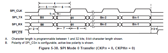
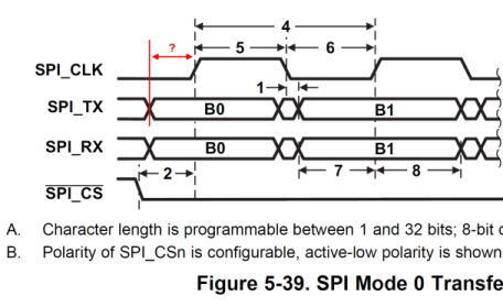
Hello, looking at figure 5-38 from the C5505 datasheet, when operating in SPI mode 0, is there a specification that indicates when SPI_TX data becomes valid with respect to the first rising clock edge (sampling of bit B0 in the diagram)? This is needed to guarantee the RX setup time of the connected device.

Thanks - AM

  • Hi,

    As mentioned in the SPI user guide (Sprufo3) : In SPI mode 0 , Clock polarity is Active low (base value of clock is low) - Data shifted out on the falling edge, inputs captured on the rising edge.

    With respect to the slave setup time requirement : Refer to the below post:

    http://e2e.ti.com/support/dsp/c5000/f/109/p/313662/1191679.aspx#1191679

    Hope the information helps.


  • Hi Vasantha, if I could ask in a different way, would it be possible to determine how long is SPI_TX is valid before the first rising clock edge when in SPI mode 0? I have noted the measurement of interest in the image below.

    Thanks!

  • Hi,

     As mentioned in the SPI User  guide, The chip select pin specified in SPICMD2 will be activated as soon as the first character transfer is initiated. The chip select pin will remain activated until all the characters specified by FLEN have been transferred.

    And the SPI module automatically delays the first clock edge with respect to the activation of the SPI_CSn pin by half a SPI_CLK cycle plus a system clock cycle. Additional clock delay cycles can be added using the data delay bits (DDn) of SPIDCR1 and SPIDCR2.

    So the timing SPI_TX -> SPI_CLK, you are looking for can be calculated based on your SPI clock and the System clock frequency.

    In C5505 Datasheet wouldn't specify the specific timing information that you are looking for.

    Hope this helps.