This thread has been locked.

If you have a related question, please click the "Ask a related question" button in the top right corner. The newly created question will be automatically linked to this question.

Problems with GPIO on TMS320C6748

Other Parts Discussed in Thread: OMAPL138, TMS320C6748

Hi all,

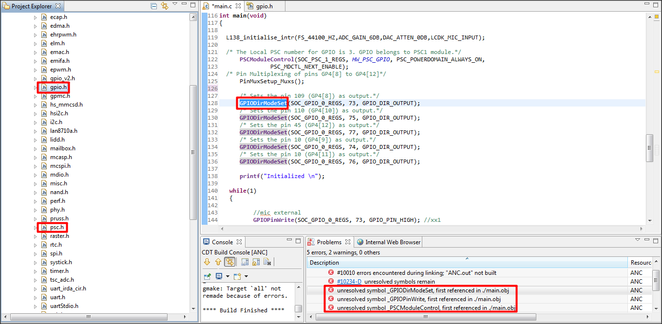
I'm confused with the example given to use GPIO. I'm trying to set more than one GPIO pin as output. Which exemple should I follow? The example for LEDs or the Gpio_example.c on the pdk_OMAPL138_1_01_00_02? Because they define the GPIO in different ways.

I have the C6748_StarterWare_1_20_04_01 on my computer and I don't have the file "lcdkOMAPL138.h", which I should include in my main. Where could I get it? I have the "lcdkC6748.h". Is it the same file?

On the other hand, I get these errors on the debugging:

Description    Resource    Path    Location    Type
unresolved symbol _GPIODirModeSet, first referenced in ./main.obj    ANC             C/C++ Problem
Description    Resource    Path    Location    Type
unresolved symbol _GPIOPinWrite, first referenced in ./main.obj    ANC             C/C++ Problem
Description    Resource    Path    Location    Type
unresolved symbol _PSCModuleControl, first referenced in ./main.obj    ANC             C/C++ Problem

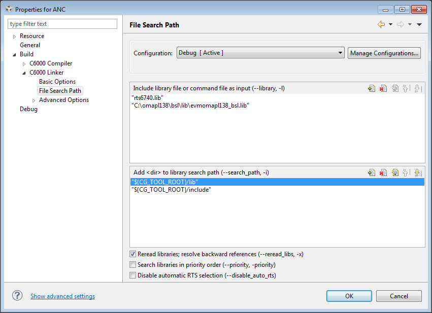
Why do I get them? They are first referenced on the main function of my program... It seems to say that the library is not included, but I think it is included. How can I solve it?

BTW, I found this on the TI wiki:

To write to multiple pins in the same bank at a time, use the API GPIOBankPinsWrite (). How can I use this sentence?

Thanks a lot,

Miguel.


  • Hi Miguel,

    Miguel says said:
    Confused with the example given to use GPIO. I'm trying to set more than one GPIO pin as output. Which exemple should I follow? The example for LEDs or the Gpio_example.c on the pdk_OMAPL138_1_01_00_02? Because they define the GPIO in different ways.

    You can refer any examples which has the configurion of GPIO pin as output. whether it is TI starterware or CSL package, it doesnot matter.  I would like to know, in what way you expect and In what way the examples are defined?

    Miguel says said:
    I have the C6748_StarterWare_1_20_04_01 on my computer and I don't have the file "lcdkOMAPL138.h", which I should include in my main. Where could I get it? I have the "lcdkC6748.h". Is it the same file?

    First of all, on which board you are trying to experiment? with which GPIO example of what package?

    1.  If it is C6748 LCDK board, use the starterware package of C6748.

    2. If it is the OMAPL138 LCDK board, use either the starterware package of OMAPl138 or the MCSDK package 1.01

    3. If it is a custom board, refer the examples and modify the code according to your needs.

    Miguel says said:
    On the other hand, I get these errors on the debugging.

    Once you answer my second question above we will discuss your third question on errors while debugging.


    Regards,

    Shankari


    -------------------------------------------------------------------------------------------------------

    Please click the Verify Answer button on this post if it answers your question.
    --------------------------------------------------------------------------------------------------------

  • Hi Shankari,

    I'm using the TMS320C6748 LCDK board, but I thought it was the same as OMAPL138... I'm using some evmoampl138_bsl.lib for the linker.

    I've been following this example:

    /**
    * \file    gpio_flip.c
    *
    * \brief   This is a sample application file demonstrating the use of
    *          a GPIO pin for input (DIP switch) and output (LED)
    *
    *
    * Copyright (C) 2012 Texas Instruments Incorporated - http://www.ti.com/
    *
    *  Redistribution and use in source and binary forms, with or without
    *  modification, are permitted provided that the following conditions
    *  are met:
    *
    *    Redistributions of source code must retain the above copyright
    *    notice, this list of conditions and the following disclaimer.
    *
    *    Redistributions in binary form must reproduce the above copyright
    *    notice, this list of conditions and the following disclaimer in the
    *    documentation and/or other materials provided with the  
    *    distribution.
    *
    *    Neither the name of Texas Instruments Incorporated nor the names of
    *    its contributors may be used to endorse or promote products derived
    *    from this software without specific prior written permission.
    *
    *  THIS SOFTWARE IS PROVIDED BY THE COPYRIGHT HOLDERS AND CONTRIBUTORS
    *  "AS IS" AND ANY EXPRESS OR IMPLIED WARRANTIES, INCLUDING, BUT NOT
    *  LIMITED TO, THE IMPLIED WARRANTIES OF MERCHANTABILITY AND FITNESS FOR
    *  A PARTICULAR PURPOSE ARE DISCLAIMED. IN NO EVENT SHALL THE COPYRIGHT
    *  OWNER OR CONTRIBUTORS BE LIABLE FOR ANY DIRECT, INDIRECT, INCIDENTAL,
    *  SPECIAL, EXEMPLARY, OR CONSEQUENTIAL DAMAGES (INCLUDING, BUT NOT
    *  LIMITED TO, PROCUREMENT OF SUBSTITUTE GOODS OR SERVICES; LOSS OF USE,
    *  DATA, OR PROFITS; OR BUSINESS INTERRUPTION) HOWEVER CAUSED AND ON ANY
    *  THEORY OF LIABILITY, WHETHER IN CONTRACT, STRICT LIABILITY, OR TORT
    *  (INCLUDING NEGLIGENCE OR OTHERWISE) ARISING IN ANY WAY OUT OF THE USE
    *  OF THIS SOFTWARE, EVEN IF ADVISED OF THE POSSIBILITY OF SUCH DAMAGE.
    */
    #include<stdio.h>
    #include "gpio.h"
    #include "psc.h"
    #include "soc_OMAPL138.h"
    #include "lcdkOMAPL138.h"
    /* HW Macros */
    #include "hw_types.h"
    /* System Defines */
    #include "lcdkOMAPL138.h"
    #include "soc_OMAPL138.h"
    #include "hw_syscfg0_OMAPL138.h"
    /* Switch Configuration */
    /* Titus : GP0[1] to GP0[4] is mapped to SW1[3:4] on OMAPL138/C6748 LCDK boards */
    /* Pin Multiplexing bit mask to select GP0[1] to GP0[4] pin. */
    #define PINMUX1_GPIO0_1_ENABLE    (SYSCFG_PINMUX1_PINMUX1_27_24_GPIO0_1  << \
                                        SYSCFG_PINMUX1_PINMUX1_27_24_SHIFT)
    #define PINMUX1_GPIO0_2_ENABLE    (SYSCFG_PINMUX1_PINMUX1_23_20_GPIO0_2  << \
                                        SYSCFG_PINMUX1_PINMUX1_23_20_SHIFT)
    #define PINMUX1_GPIO0_3_ENABLE    (SYSCFG_PINMUX1_PINMUX1_19_16_GPIO0_3  << \
                                        SYSCFG_PINMUX1_PINMUX1_19_16_SHIFT)
    #define PINMUX1_GPIO0_4_ENABLE    (SYSCFG_PINMUX1_PINMUX1_15_12_GPIO0_4  << \
                                        SYSCFG_PINMUX1_PINMUX1_15_12_SHIFT)
    /* LED Configuration */
    /* Titus : GP6[12], GP6[13], GP2[12] and GP0[9] is mapped to D4, D5, D6, D7 LEDs on OMAPL138/C6748 LCDK boards */
    /* Pin Multiplexing bit mask to select GP6[12] pin. */
    #define PINMUX13_GPIO6_12_ENABLE    (SYSCFG_PINMUX13_PINMUX13_15_12_GPIO6_12  << \
                                        SYSCFG_PINMUX13_PINMUX13_15_12_SHIFT)
    /* Pin Multiplexing bit mask to select GP6[13] pin. */
    #define PINMUX13_GPIO6_13_ENABLE    (SYSCFG_PINMUX13_PINMUX13_11_8_GPIO6_13  << \
                                        SYSCFG_PINMUX13_PINMUX13_11_8_SHIFT)
    /* Pin Multiplexing bit mask to select GP2[12] pin. */
    #define PINMUX5_GPIO2_12_ENABLE    (SYSCFG_PINMUX5_PINMUX5_15_12_GPIO2_12  << \
                                        SYSCFG_PINMUX5_PINMUX5_15_12_SHIFT)
    /* Pin Multiplexing bit mask to select GP0[9] pin. */
    #define PINMUX0_GPIO0_9_ENABLE    (SYSCFG_PINMUX0_PINMUX0_27_24_GPIO0_9  << \
                                        SYSCFG_PINMUX0_PINMUX0_27_24_SHIFT)
    void PinMuxSetup_leds(void)
    {
         unsigned int savePinmux = 0;
         /*
         ** Clearing the bit in context and retaining the other bit values
         ** in PINMUX13 register.
         */
         savePinmux = (HWREG(SOC_SYSCFG_0_REGS + SYSCFG0_PINMUX(13)) &
                      ~(SYSCFG_PINMUX13_PINMUX13_15_12));
         /* Setting the pins corresponding to GP6[12] in PINMUX13 register.*/
         HWREG(SOC_SYSCFG_0_REGS + SYSCFG0_PINMUX(13)) =
              (PINMUX13_GPIO6_12_ENABLE | savePinmux);
         /*
         ** Clearing the bit in context and retaining the other bit values
         ** in PINMUX13 register.
         */
         savePinmux = (HWREG(SOC_SYSCFG_0_REGS + SYSCFG0_PINMUX(13)) &
                      ~(SYSCFG_PINMUX13_PINMUX13_11_8));
         /* Setting the pins corresponding to GP6[13] in PINMUX13 register.*/
         HWREG(SOC_SYSCFG_0_REGS + SYSCFG0_PINMUX(13)) =
              (PINMUX13_GPIO6_13_ENABLE | savePinmux);
         /*
         ** Clearing the bit in context and retaining the other bit values
         ** in PINMUX5 register.
         */
         savePinmux = (HWREG(SOC_SYSCFG_0_REGS + SYSCFG0_PINMUX(5)) &
                      ~(SYSCFG_PINMUX5_PINMUX5_15_12));
         /* Setting the pins corresponding to GP2[12] in PINMUX5 register.*/
         HWREG(SOC_SYSCFG_0_REGS + SYSCFG0_PINMUX(5)) =
              (PINMUX5_GPIO2_12_ENABLE | savePinmux);
         /*
         ** Clearing the bit in context and retaining the other bit values
         ** in PINMUX0 register.
         */
         savePinmux = (HWREG(SOC_SYSCFG_0_REGS + SYSCFG0_PINMUX(0)) &
                      ~(SYSCFG_PINMUX0_PINMUX0_27_24));
         /* Setting the pins corresponding to GP0[9] in PINMUX0 register.*/
         HWREG(SOC_SYSCFG_0_REGS + SYSCFG0_PINMUX(0)) =
              (PINMUX0_GPIO0_9_ENABLE | savePinmux);
    }
    void PinMuxSetup_switches(void)
    {
         unsigned int savePinmux = 0;
         /* Setting the pins corresponding to GP0[1] in PINMUX1 register.*/
         /*
         ** Clearing the bit in context and retaining the other bit values
         ** in PINMUX1 register.
         */
         savePinmux = (HWREG(SOC_SYSCFG_0_REGS + SYSCFG0_PINMUX(1)) &
                      ~(SYSCFG_PINMUX1_PINMUX1_27_24));
         HWREG(SOC_SYSCFG_0_REGS + SYSCFG0_PINMUX(1)) =
              (PINMUX1_GPIO0_1_ENABLE | savePinmux);
         /* Setting the pins corresponding to GP0[2] in PINMUX1 register.*/
              /*
              ** Clearing the bit in context and retaining the other bit values
              ** in PINMUX1 register.
              */
              savePinmux = (HWREG(SOC_SYSCFG_0_REGS + SYSCFG0_PINMUX(1)) &
                           ~(SYSCFG_PINMUX1_PINMUX1_23_20));
              HWREG(SOC_SYSCFG_0_REGS + SYSCFG0_PINMUX(1)) =
                   (PINMUX1_GPIO0_2_ENABLE | savePinmux);
              /* Setting the pins corresponding to GP0[3] in PINMUX1 register.*/
                   /*
                   ** Clearing the bit in context and retaining the other bit values
                   ** in PINMUX1 register.
                   */
                   savePinmux = (HWREG(SOC_SYSCFG_0_REGS + SYSCFG0_PINMUX(1)) &
                                ~(SYSCFG_PINMUX1_PINMUX1_19_16));
                   HWREG(SOC_SYSCFG_0_REGS + SYSCFG0_PINMUX(1)) =
                        (PINMUX1_GPIO0_3_ENABLE | savePinmux);
                   /* Setting the pins corresponding to GP0[4] in PINMUX1 register.*/
                        /*
                        ** Clearing the bit in context and retaining the other bit values
                        ** in PINMUX1 register.
                        */
                        savePinmux = (HWREG(SOC_SYSCFG_0_REGS + SYSCFG0_PINMUX(1)) &
                                     ~(SYSCFG_PINMUX1_PINMUX1_15_12));
                        HWREG(SOC_SYSCFG_0_REGS + SYSCFG0_PINMUX(1)) =
                             (PINMUX1_GPIO0_4_ENABLE | savePinmux);
    }
    int main(void)
    {
        /* The Local PSC number for GPIO is 3. GPIO belongs to PSC1 module.*/
        PSCModuleControl(SOC_PSC_1_REGS, HW_PSC_GPIO, PSC_POWERDOMAIN_ALWAYS_ON,
                 PSC_MDCTL_NEXT_ENABLE);
        /* Pin Multiplexing of pins GP0[1] to GP0[4] of GPIO Bank 2 for DIP SWITCHEs in OMAPL138 LCDK board */
        PinMuxSetup_switches();
        /* Pin Multiplexing of pins GP6[12], GP6[13], GP2[12], GP0[9], for LEDs in OMAPL138 LCDK board */
        PinMuxSetup_leds();
        /* Titus : 2,3,4,5 is the GPIO no for GP0[1] to GP0[4]; Refer page no 901 in OMAPL138/C6748 TRM */
    /* SWITCHEs SETUP */
        /* Sets the pin 2 (GP0[1]) as input.*/
        GPIODirModeSet(SOC_GPIO_0_REGS, 2, GPIO_DIR_INPUT);
        /* Sets the pin 3 (GP0[2]) as input.*/
        GPIODirModeSet(SOC_GPIO_0_REGS, 3, GPIO_DIR_INPUT);
        /* Sets the pin 4 (GP0[3]) as input.*/
        GPIODirModeSet(SOC_GPIO_0_REGS, 4, GPIO_DIR_INPUT);
        /* Sets the pin 5 (GP0[4]) as input.*/
        GPIODirModeSet(SOC_GPIO_0_REGS, 5, GPIO_DIR_INPUT);
    /* LEDs SETUP */
        /* Sets the pin 109 (GP6[12]) as output.*/
        GPIODirModeSet(SOC_GPIO_0_REGS, 109, GPIO_DIR_OUTPUT);
        /* Sets the pin 110 (GP6[13]) as output.*/
        GPIODirModeSet(SOC_GPIO_0_REGS, 110, GPIO_DIR_OUTPUT);
        /* Sets the pin 45 (GP2[12]) as output.*/
        GPIODirModeSet(SOC_GPIO_0_REGS, 45, GPIO_DIR_OUTPUT);
        /* Sets the pin 10 (GP0[9]) as output.*/
        GPIODirModeSet(SOC_GPIO_0_REGS, 10, GPIO_DIR_OUTPUT);
        while(1)
        {
        /* Titus : 2,3,4,5 is the GPIO no for GP0[1] to GP0[4]; Refer page no 901 in OMAPL138/C6748 TRM */
            if (GPIOPinRead(SOC_GPIO_0_REGS, 2))
            {
            GPIOPinWrite(SOC_GPIO_0_REGS, 109, GPIO_PIN_LOW);
            printf("S1 is not pressed\n");
            }
            else
            {//TODO/* Hi Mus: Put your flip code here for 90' */
                printf("S1 is pressed\n");
                GPIOPinWrite(SOC_GPIO_0_REGS, 109, GPIO_PIN_HIGH);
            }
            if (GPIOPinRead(SOC_GPIO_0_REGS, 3))
            {
            GPIOPinWrite(SOC_GPIO_0_REGS, 110, GPIO_PIN_LOW);
            printf("S2 is not pressed\n");
            }
            else
                    {//TODO/* Hi Mus: Put your flip code here for 180' */
                        printf("S2 is pressed\n");
                        GPIOPinWrite(SOC_GPIO_0_REGS, 110, GPIO_PIN_HIGH);
                    }
            if (GPIOPinRead(SOC_GPIO_0_REGS, 4))
            {
            GPIOPinWrite(SOC_GPIO_0_REGS, 45, GPIO_PIN_LOW);
            printf("S3 is not pressed\n");
            }
            else
                    {//TODO/* Hi Mus: Put your flip code here for 270' */
                        printf("S3 is pressed\n");
                        GPIOPinWrite(SOC_GPIO_0_REGS, 45, GPIO_PIN_HIGH);
                    }
            if (GPIOPinRead(SOC_GPIO_0_REGS, 5))
            {
            GPIOPinWrite(SOC_GPIO_0_REGS, 10, GPIO_PIN_LOW);
            printf("S4 is not pressed\n");
            }
            else
                    {//TODO/* Hi Mus: Put your flip code here for 0' or 360'' */
                        printf("S4 is pressed\n");
                        GPIOPinWrite(SOC_GPIO_0_REGS, 10, GPIO_PIN_HIGH);
                    }
        }
    }
    I don't know very well the difference between C6748 and OMAPL138... Am I following the wrong example?
    Regards,
    Miguel.
  • Miguel,

    The file you pasted here is not the original software released by TI.

    In the above pasted source file, I could see comments like "/* Titus or ?*To Do Mus" e.t.c., which means it is a modified code. I guess, you are asking us, why the modified code is not working. Forum members may not know what is modified and why it is modified in the original sample source code of GPIO. Without that, we may not be able to understand what the real problem is and provide solutions.

    Miguel says said:
    I don't know very well the difference between C6748 and OMAPL138... Am I following the wrong example?

    You didnot mention the name of the software package you are using. You have given only the file content of a file, gpio_flip.c. In the C6748 starterware package I do not find any file by name "gpio_flip.c"

    The OMAPl138 is a ARM + DSP device. The C6748 is a DSP device. The DSP core on OMAPL138 is C6748.

    If you are looking for a GPIO example which are already working and tested on C6748 LCDK, please download the package, C6748 starterware from the below link and try to successfully run the GPIO example first. It is always good to start with something which already works and gradually you can modify as per your project needs.

    http://processors.wiki.ti.com/index.php/StarterWare - Download the version 01.20.04.01

    After installing the starterware package, you will find the GPIO example's project files at path, "..\Program Files\Texas Instruments\pdk_C6748_2_0_0_0\C6748_StarterWare_1_20_03_03\examples\lcdkC6748\gpio" and  follow this TI WIKI to import, build and run the (GPIO) examples using CCS.

    http://processors.wiki.ti.com/index.php/Importing_Projects_into_CCS

    Follow the below link on target set up to run examples on C6748 LCDK board.

    http://processors.wiki.ti.com/index.php/L138/C6748_Development_Kit_(LCDK)


    Regards,

    Shankari

    -------------------------------------------------------------------------------------------------------

    Please click the Verify Answer button on this post if it answers your question.
    --------------------------------------------------------------------------------------------------------

  • Hi Shankari,

    I think this code is fine, but I'm missing some library or something. Any way, I will try with the code from the starter ware and I'll let you know.

    Thanks,

    Miguel.

  • I have checked the example you told me and it is very similar to the one I'm using. It defines the GPIO as the same way as the example I pasted before. I have no CCS project on the folder you told me, I only have the C code file and the libraries included on it are:

    #include "gpio.h"
    #include "psc.h"
    #include "soc_C6748.h"
    #include "lcdkC6748.h"


    I have the same ones on my project and it isn't working, so I think I have some kind of problem on the File Search Path of my linker file. Could you tell me what should be in there?

    If follow the example given on "C:\ti\pdk_OMAPL138_1_01_00_02\packages\ti\csl\example\omapl138-lcdk\gpio\src" I have the same errors on the debugging process. It has to be something missing on the linker file search path.

    Regards,

    Miguel.

  • Hi Miguel,

    First let us go one by one. The first step for you is to run the example successfully and not the modified one as of now!!.

    1. You will find the CCS project files of GPIO example at "C:\Program Files\Texas Instruments\pdk_C6748_2_0_0_0\C6748_StarterWare_1_20_03_03\build\c674x\cgt_ccs\c6748\lcdkC6748\gpio"

    2. Try to import it by following the WIKI link in my previous post. and let me know you are able to run it successfully.


    I may not be able to help you if you think it is difficult to follow my instructions.


    Regards,

    Shankari

    -------------------------------------------------------------------------------------------------------

    Please click the Verify Answer button on this post if it answers your question.
    --------------------------------------------------------------------------------------------------------

  • Hi,

    I've imported the project you are telling me and I can't make it work. I get this error:

    Description    Resource    Path    Location    Type
    gmake: *** No rule to make target `C:/examples/lcdkC6748/gpio/gpioCardDetect.c', needed by `gpioCardDetect.obj'.    gpio_c674x_c6748_lcdkC6748        Unknown    C/C++ Problem

    I also have this warnings:

    Description    Resource    Path    Location    Type
    Invalid project path: Include path not found (C:\nandlib\include).    gpio_c674x_c6748_lcdkC6748        pathentry    Path Entry Problem
    Invalid project path: Include path not found (C:\include\hw).    gpio_c674x_c6748_lcdkC6748        pathentry    Path Entry Problem
    Invalid project path: Include path not found (C:\include\c674x).    gpio_c674x_c6748_lcdkC6748        pathentry    Path Entry Problem
    Invalid project path: Include path not found (C:\include).    gpio_c674x_c6748_lcdkC6748        pathentry    Path Entry Problem
    Invalid project path: Include path not found (C:\usblib\include).    gpio_c674x_c6748_lcdkC6748        pathentry    Path Entry Problem
    Invalid project path: Include path not found (C:\ipclite\include).    gpio_c674x_c6748_lcdkC6748        pathentry    Path Entry Problem
    Invalid project path: Include path not found (C:\include\c674x\c6748).    gpio_c674x_c6748_lcdkC6748        pathentry    Path Entry Problem
    Invalid project path: Include path not found (C:\grlib\include).    gpio_c674x_c6748_lcdkC6748        pathentry    Path Entry Problem

    Do you have any idea of why this is happening?

    Regards,

    Miguel.

  • Are you compiling within the installed StarterWare folder? Sounds like have copied out the gpio example and compiled away from the the installed folder. Or perhaps your install did not fully complete. Maybe uninstall and reinstall.

    If you doing strictly bare-metal work, I'd suggest you download the standalone StarterWare package instead using the StarterWare folder within the PDK. Shankar gave a link to the StarterWare webpage. The StarterWarer version you are using is not the latest. Suggest you download the latest.

  • Do I have to switch the workspace of my CCS for using the example code? Because I've just imported the project into my workspace. If this is the problem, which workspace should I use?

    Thanks.

  • Importing multiple projects into one workspace should not be a problem. It it just time consuming as a "build all" will build all the projects. I usually have one project for each workspace to avoid accidentally building other projects.

  • Okay, so I we'll follow with my workspace. The project I've imported is in: C:\ti\C6748_StarterWare_1_20_04_01\build\c674x\cgt_ccs\c6748\lcdkC6748\gpio

    Is it correct?

    Also, I'm having this error when I try to open (on CCS) the file gpioCardDetect.c:

    Error retrieving content description for resource '/gpio_c674x_c6748_lcdkC6748/gpioCardDetect.c'

    Thanks.

  • No idea why that is happening. The project has relative paths up and down to the source  and binaries. Here's some instructions I gave in another thread with various bits changed to reflect you situation. I've tested this with CCS 5.2.

    - Start CCS
    - The "Workspace Launcher" dialog is displayed
    - Enter a path into "Workspace" text. The path should not exist so that new workspace is created.
    - "Code Composer Studio" application eventually launches.
    - Close the "TI Resource Explorer" sub-window
    - Select menu "Project->Import Existing CCS Eclipse" Project
    - The "Import CCS Eclipse Project" dialog is displayed.
    - Use "Select search-directory" option.
    - Browse to StarterWare build directory. In your case, something like
    C:\ti\C6748_StarterWare_1_20_04_01\build\c674x\cgt_ccs\c6748\lcdkC6748\gpio
    - In the "Discovered projects:" list, there should be one item. DO NOT check box "Copy projects into workspace". DO NOT check box "Automatically import..".
    - Click "Finish". The "Import CCS Eclipse Project" dialog closes.
    - In the "Project Explorer" sub-window, click on the item "gpio_c674x_c6748_lcdkC6748". The project must be selected before project menu items are enabled.
    - Select menu "Project->Build All"
    - See bUild messages in the "Console" sub-window.
    - Select menu "Project->Debug".
    - The "Open Target Configuration" should be displayed.
    - Select connection and emulator.
    - In the "Project Explorer" sub-window, click on the item "gpio_c674x_c6748_lcdkC6748" again.
    - Select menu "Project->Debug". Code should load at this point.

  • That worked for me!!! Now which should be the next step?

  • That is up to you. Try out the example. Review the code. Look at other example that use GPIOs. The "demo" example has a LED via gpio code as part of it's many demos.

    A polite reminder that this forum is not really a tutorial service. Try to post one specific problem per thread. The problems should be a specific as possible. Close the thread when you have a solution. People tend to avoid "Support Me Forever For All My Problems" threads.

  • I have another question. I've seen that the example code has the function "GPIOBank6Pin12PinMuxSetup();" and it is defined on the lcdkC6748.h file where says "extern void GPIOBank6Pin12PinMuxSetup(void);" What should I do if I want to use the five GPIO pins between GP4[8] and GP4[12]?

    Thanks.

  • The function GPIOBank6Pin12PinMuxSetup() is specific to the LCDK platform.
    C:\ti\C6748_StarterWare_1_20_04_01\platform\lcdkC6748\gpio.c
    That code is in a library. Modifying that library would probably open up more build problems. It easier to just cut and paste the code into a source file in your project. Use defined in this file as reference:

    C:\ti\C6748_StarterWare_1_20_04_01\include\hw\hw_syscfg0_C6748.h

    StarterWare MUX definitions are very repetitive and follow a pattern. Get one right and repeat. Code would be something like this:

    void GPIOBank4Pin8toPin12PinMuxSetup(void)
    {
      unsigned int v;

      // Get current value
      v  = HWREG(SOC_SYSCFG_0_REGS + SYSCFG0_PINMUX(9));

      // Clear field then set field to desired value
      v &=  SYSCFG_PINMUX9_PINMUX9_31_28;
      v |= (SYSCFG_PINMUX9_PINMUX9_31_28_GPIO4_8
        <<  SYSCFG_PINMUX9_PINMUX9_31_28_SHIFT);

      v &=  SYSCFG_PINMUX9_PINMUX9_27_24;
      v |= (SYSCFG_PINMUX9_PINMUX9_27_24_GPIO4_9
         << SYSCFG_PINMUX9_PINMUX9_27_24_SHIFT);

      v &=  SYSCFG_PINMUX9_PINMUX9_23_20;
      v |= (SYSCFG_PINMUX9_PINMUX9_23_20_GPIO4_10
         << SYSCFG_PINMUX9_PINMUX9_23_20_SHIFT);

      v &=  SYSCFG_PINMUX9_PINMUX9_19_16;
      v |= (SYSCFG_PINMUX9_PINMUX9_19_16_GPIO4_11
         << SYSCFG_PINMUX9_PINMUX9_19_16_SHIFT);

      v &=  SYSCFG_PINMUX9_PINMUX9_15_12;
      v |= (SYSCFG_PINMUX9_PINMUX9_15_12_GPIO4_12
         << SYSCFG_PINMUX9_PINMUX9_15_12_SHIFT);

      / Save changed value
      HWREG(SOC_SYSCFG_0_REGS + SYSCFG0_PINMUX(9)) = v;

    }

    This is very similiar to the Titus gave you. Study his example. Good luck.

    EDIT: Correct 10 to 9. Cut'n'paste error.

  • OK, now I think the GPIO are defined and should work. But I'm also trying to use the audio codec "L138_LCDK_aic3106_init.h" using poll functions. I have linked to the project the L138_LCDK_aic3106_init.h, the L138_LCDK_aic3106_init.h and the vectors_poll.asm files. On the building process I get this error:

    could not open source file "L138_LCDK_aic3106_init.h"    gpioCardDetect.c   

    Do you know why I'm getting this error? Is it for some undeclared library on the include options of the C6000 Compiler or on the File search path of the C6000 linker?


    Thanks.

  • Sounds like your GPIO problem has been resolved. Please close this thread and start a new thread. You need to give more detail to your problem.