This thread has been locked.

If you have a related question, please click the "Ask a related question" button in the top right corner. The newly created question will be automatically linked to this question.

OMAP L138 SPI1 Problems

Other Parts Discussed in Thread: SYSBIOS, OMAPL138

Hello All,

I am using LogicPD Omap L138 SOM on a custom board, SysBios 6.34.2.18, XDCTools 3.23.5.61, StarterWare 1.10.03.03.

I try communicating with a sensor trough SPI1 over the ARM9 core:

1. Pinmux is configured correctly (PINMUX4 = 0x01000000, PINMUX5 = 0x00110100)

2. CS 3 is used

3. SPI Freq is 350KHz

4. Char length is 16bits, MSB first, Polarity HIGH, Phase LOW (As the sensor DS requires).

I have some problems:

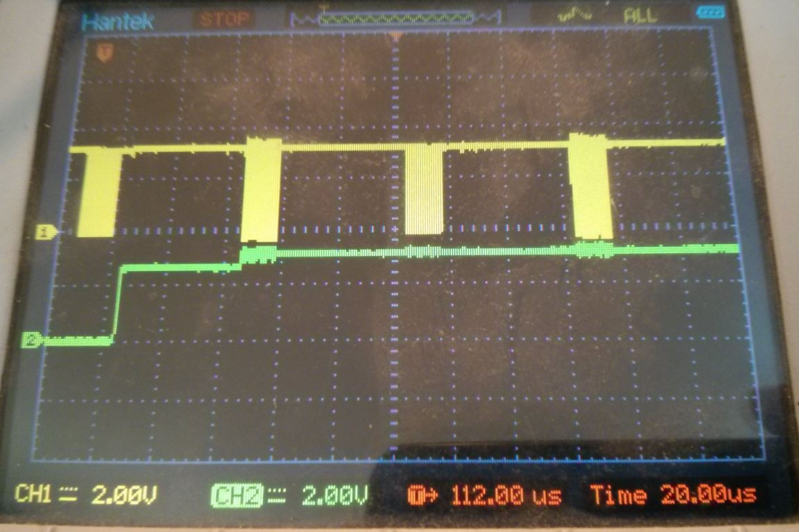
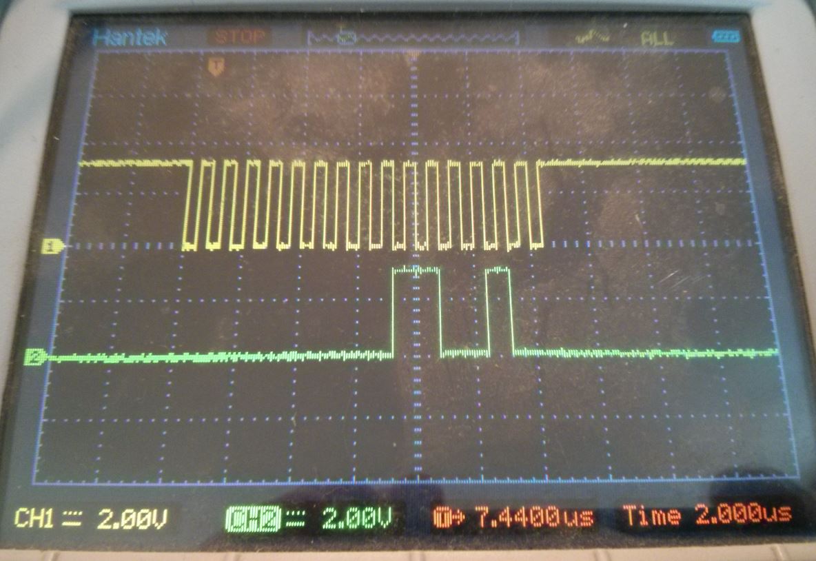
1. SOMI line is LOW when no data is transferred but when data is transferred it is pulled HIGH (I can see some data higher than the flat line). I looked into LogicPD SOM schematics also in my custom board and couldn't find any interference. 

2. Why do the processor send ~64 clocks for 2 bytes of transferred data? (Shouldn't it be 16 clocks for send and 16 clocks for receive?).

Here is my code:

#define SIMO_SOMI_CLK_CS        0x00000E00
#define CHAR_LENGTH             0x10
#define CSNum 		3//2
#define SPI_INT		SYS_INT_SPINT1
#define SPI_BASE	SOC_SPI_1_REGS

volatile unsigned int flag = 1;
volatile unsigned int is_ok = 0;
volatile unsigned char tx_flag = 0;
int len;
unsigned int tx_len;
unsigned int rx_len;
unsigned int tx_data[2000];
unsigned int rx_data[26000];
#pragma DATA_SECTION(tx_data,"EXTRAM");
#pragma DATA_SECTION(rx_data,"EXTRAM");
unsigned int *p_tx;
unsigned int *p_rx;

Void main()
{ 
    Task_Params taskParams;

    /* Create two tasks that share a resource*/
    Task_Params_init(&taskParams);
    taskParams.priority = 1;
    tsk1 = Task_create (task1, &taskParams, NULL);

    SPIInitialize();
    BIOS_start();
}
/******************************************************************************
**                      INTERNAL FUNCTION DEFINITIONS
*******************************************************************************/
Void task1(UArg arg0, UArg arg1)
{
    ReadData();

    while(rx_len<128)
    {
    }
}
void ReadData(void)
{
    tx_data[0] = 100; // This asks the sensor for config data, Data is received from external interrupt.
    len = 1;
    SPIDat1Config(SPI_BASE, (SPI_CSHOLD | SPI_DATA_FORMAT0), DCS);
    SpiTransfer();
}

/*
** Enables SPI Transmit and Receive interrupt.
** Deasserts Chip Select line.
*/
void  SpiTransfer(void)
{
    p_tx = &tx_data[0];
    p_rx = &rx_data[0];
    SPIIntEnable(SPI_BASE, (SPI_RECV_INT | SPI_TRANSMIT_INT));
    while(flag);
    flag = 1;
    /* Deasserts the CS pin(line) */
    //SPIDat1Config(SOC_SPI_1_REGS, SPI_DATA_FORMAT0, DCS);
}

/*
** Data transmission and receiption SPIIsr
**
*/
void SPIIsr(void)
{
    IntSystemStatusClear(SPI_INT);
    unsigned int intCode = SPIInterruptVectorGet(SPI_BASE);

    while (intCode)
    {
        if(intCode == SPI_TX_BUF_EMPTY)
        {
            len--;
            SPITransmitData1(SPI_BASE, *p_tx);
            p_tx++;
            if (!len)
            {
                SPIIntDisable(SPI_BASE, SPI_TRANSMIT_INT);
            }
        }

        if(intCode == SPI_RECV_FULL)
        {
        	int rec = SPIDataReceive(SPI_BASE);
        	*p_rx = (short)rec;
        	p_rx++;
        	rx_len++;
        	if (!len)
        	{
        		flag = 0;
        		SPIIntDisable(SPI_BASE, SPI_RECV_INT);
        	}
        }
        intCode = SPIInterruptVectorGet(SPI_BASE);
    }
}

/*
** Configures Data Format register of SPI
**
*/
void SPIConfigDataFmtReg(unsigned int dataFormat, unsigned int baseAdd)
{
    SPIConfigClkFormat(baseAdd,
                       (SPI_CLK_POL_HIGH | SPI_CLK_INPHASE),
                       dataFormat);

    /* Configures SPI to transmit MSB bit First during data transfer */
    SPIShiftMsbFirst(baseAdd, dataFormat);

    /* Sets the Charcter length */
    SPICharLengthSet(baseAdd, CHAR_LENGTH, dataFormat);
}

/*
** Initialization of SPI1 Instance is done here.
*/
void SPIInitialize(void)
{
	flagTx = 0;
	flagRx = 0;
	int spiInstance = 0;
#ifndef SPI_0
	spiInstance = 1;
#endif

	if(spiInstance == 0)
	{
		PSCModuleControl(SOC_PSC_0_REGS, HW_PSC_SPI0, PSC_POWERDOMAIN_ALWAYS_ON,
				PSC_MDCTL_NEXT_ENABLE);
	}
	else if(spiInstance==1)
	{
		PSCModuleControl(SOC_PSC_1_REGS, HW_PSC_SPI1, PSC_POWERDOMAIN_ALWAYS_ON,
				PSC_MDCTL_NEXT_ENABLE);
	}

    PSCModuleControl(SOC_PSC_1_REGS, HW_PSC_GPIO, PSC_POWERDOMAIN_ALWAYS_ON,
                     PSC_MDCTL_NEXT_ENABLE);

    /* Using SPI1 instance. */
    SPIPinMuxSetup(spiInstance);

    /* Select CS0 of SPI0. The SPI Flash is connected to SPI0_SCS[0]. */
	if(spiInstance == 0)
	{
	    SPI0CSPinMuxSetup(CSNum);
	}
	else if(spiInstance==1)
	{
	    SPI1CSPinMuxSetup(CSNum);
	}

    SPISetUp(SPI_BASE);
}

/*
** Configures the SPI1 instance for communication.
*/
void SPISetUp(unsigned int baseAdd)
{
    unsigned int  val = SIMO_SOMI_CLK_CS | DCS;

    SPIReset(baseAdd);

    SPIOutOfReset(baseAdd);

    SPIModeConfigure(baseAdd, SPI_MASTER_MODE);

    SPIPinControl(baseAdd, 0, 0, &val);

    /* Configures SPI Data Format Register */
    SPIConfigDataFmtReg(SPI_DATA_FORMAT0, baseAdd);

    SPIDefaultCSSet(baseAdd, DCS);

    SPIClkConfigure(baseAdd, SOC_SPI_1_MODULE_FREQ, 350000, SPI_DATA_FORMAT0);

     /* Selects the SPI Data format register to used and Sets CSHOLD
      * to assert CS pin(line)
      */
    SPIDat1Config(baseAdd, (SPI_CSHOLD | SPI_DATA_FORMAT0), DCS);

     /* map interrupts to interrupt line INT1 */
    SPIIntLevelSet(baseAdd, SPI_RECV_INTLVL | SPI_TRANSMIT_INTLVL);

    HWREG(baseAdd + SPI_SPIPC(1)) |= (0x00000600 | DCS);

    /* Enable SPI communication */
    SPIEnable(baseAdd);
}

Thanks for the help,

Yoel

  • It's been a while since I looked at the SPI code. I vaguely remember I had problems with the code assuming that the Tx interrupt always occured before the Rx interrupt. If the order is swapped, the code miscounts. I think the StarterWare guys realized that and fixed that in the next StarterWare release, OMAPL138 StarterWare 1_10_04_01. That release has a separate down counter for Tx and Rx. I still found problems with that release as the busy wait flag gets cleared by the Rx handler. I had to have separate Tx and Rx flags to reliably tell that a transaction had fully completed.

    On a separate note. your are using SYSBIOS, any reason for not using the PSP SPI driver. It is better integrated into the OS. Just a more resource intensive and much hard to configure. Slightly better written than the StarterWare SPI code.

  • Hey Norman,

    Thanks for the quick reply!

    I will look into the changes they made in the starterware drivers, but do you know why does the SPI clock acts as if it sends 4 words (16bit each) instead of 2? Maybe it's the standard but I havent found any reference to it...

    Furthermore, Do you know of anything that can pull the SOMI signal up? Maybe my configuration (or the driver) isn't correct..

    I started the project with starterware 2.5 years ago and then added the SYSBios. The PSP seems too complicated to work with altough I use it for the SD drivers over the DSP (Because there are no solutions in starterware over the ARM9).

    Yoel

  • No idea what you are seeing 64 clock pulses. Your code, with ReadData() len=1, should result in SPITransmitData1() being called once with a result of 16 clock pulses. Seeing 64 clock pulses implies that SPITransmitData1() was called 4 times.

    Th SOMI line should always be an input to the processor. Perhaps there is pull up resistor somewhere and slave is not capable of pulling it down.

    A programming note, your word is 16-bit. Perhaps tx_data, rx_data, p_tx and p_rx should be 16-bit types.

    SPI sends and recieves simultaneously. Is the slave sending back on the first 16 clock pulses?

  • The slave should not send data on the first word. 

    I don't have a clue why is sending so many clock pulses, I even probed the SPI1_CLK line with a scope when I put the data on the SPIDAT1 register so it must be on a single transmit call. I'll change the types to short but I don't think it matters when the drivers receive unsigned int...

    Am I the only one with this wierd behaviour?

  • Not much to add. Mystery to me. Just a side not. The prescaler can only be 8-bits.

    decirted prescale = 150000000/350000 - 1 = 427.57 = 427 = 0x1AB

    actual prescale = 0xAB + 1 = 0xAC = 172

    actual clock = 150000000/172 = 872093

  • Well, Inspite of Norman's help the problem remains.

    I did change the SPI freq to 1MHz because of the prescale overflow as norman suggested but there are still 2 main issues which I would be happy if someone from TI would step in and help:

    1. Every call to "SPITransmitData1" generates 64 clocks on the SPI1_CLK line.

    2. SPI1_SOMI line I somehow pulled to 2.8V when slave sends data (the data is at 3.3V but it is masked with a 2.8V signal), There is nothing that pulls up the line on my board nor the LogicPD som (assuming the SOM schematics are correct).

    I really need this problem fixed fast and I ran out of options.

    Yoel

  • The SPI pins, by default, all have Internal Pullup (IPU) resistors. Perhaps the slave is not strong enough to pull down the line. Yeah, unlikely.

    Can you post the current version of your test code? A thing to verify is that you initialized the transmit buffer for the entire transaction. For example, if you tx 1 byte then rx 1 bytes then you have to init 1+1=2 bytes of the tx buffer and look at the 2nd byte in the receive buffer. The SPITransmitData1() function does not mask the data argument. Any data over 16 bits will write into the control portion of SPI_SPIDAT1.

  • Hey Norman,

    The pull up doesn't happen in SPI0 so I don't think that is the reason (unless the pullups there are much smaller).

    I couldn't find a way to explicitly tell the SPI how many bytes to send for each transaction (only the word length) and I probe the SPI_CLK only before and after the "SPITransmitData1(SPI_BASE, *p_tx)" command, so it only suppose to send one word and receive one word, that is 32bit.

    Here is the code:

    #define SPI_BASE	SOC_SPI_1_REGS
    #define CSNum 		3
    #define DCS 		(1<<CSNum)
    #define SIMO_SOMI_CLK_CS        0x00000E00
    #define CHAR_LENGTH             0x10
    
    volatile unsigned int flag = 1;
    volatile unsigned int is_ok = 0;
    volatile unsigned char tx_flag = 0;
    int len;
    unsigned int tx_len;
    unsigned int rx_len;
    unsigned int tx_data[2000];
    unsigned int rx_data[26000];
    #pragma DATA_SECTION(tx_data,"EXTRAM");
    #pragma DATA_SECTION(rx_data,"EXTRAM");
    unsigned int *p_tx;
    unsigned int *p_rx;
    
    Void main()
    { 
        Task_Params taskParams;
    
        /* Create two tasks that share a resource*/
        Task_Params_init(&taskParams);
        taskParams.priority = 1;
        tsk1 = Task_create (task1, &taskParams, NULL);
    
        SPIInitialize();
        BIOS_start();
    }
    
    Void task1(UArg arg0, UArg arg1)
    {
        Task_sleep(10);
    
        rx_len = 0;
        ReadData();
    
        while(rx_len<128)
        {
        }
    }
    
    void ReadData(void)
    {
        tx_data[0] = 100;
        len = 1;
        SPIDat1Config(SPI_BASE, (SPI_CSHOLD | SPI_DATA_FORMAT0), DCS);
        SpiTransfer();
    }
    
    void  SpiTransfer(void)
    {
        p_tx = &tx_data[0];
        p_rx = &rx_data[0];
        SPIIntEnable(SPI_BASE, (SPI_RECV_INT | SPI_TRANSMIT_INT));
        while(flag);
        flag = 1;
    }
    
    void SPIIsr(void)
    {
        IntSystemStatusClear(SPI_INT);
        unsigned int intCode = SPIInterruptVectorGet(SPI_BASE);
    
        while (intCode)
        {
            if(intCode == SPI_TX_BUF_EMPTY)
            {
                len--;
                SPITransmitData1(SPI_BASE, *p_tx);
                p_tx++;
                if (!len)
                {
                    SPIIntDisable(SPI_BASE, SPI_TRANSMIT_INT);
                }
            }
    
            if(intCode == SPI_RECV_FULL)
            {
            	int rec = SPIDataReceive(SPI_BASE);
            	*p_rx = (short)rec;
            	p_rx++;
            	rx_len++;
            	if (!len)
            	{
            		flag = 0;
            		SPIIntDisable(SPI_BASE, SPI_RECV_INT);
            	}
            }
            intCode = SPIInterruptVectorGet(SPI_BASE);
        }
    }
    
    void SPIConfigDataFmtReg(unsigned int dataFormat, unsigned int baseAdd)
    {
        SPIConfigClkFormat(baseAdd,
                           (SPI_CLK_POL_HIGH | SPI_CLK_INPHASE),
                           dataFormat);
    
        /* Configures SPI to transmit MSB bit First during data transfer */
        SPIShiftMsbFirst(baseAdd, dataFormat);
    
        /* Sets the Charcter length */
        SPICharLengthSet(baseAdd, CHAR_LENGTH, dataFormat);
    }
    
    void SPIInitialize(void)
    {
    	flagTx = 0;
    	flagRx = 0;
    	int spiInstance = 0;
    #ifndef SPI_0
    	spiInstance = 1;
    #endif
    
    	if(spiInstance == 0)
    	{
    		PSCModuleControl(SOC_PSC_0_REGS, HW_PSC_SPI0, PSC_POWERDOMAIN_ALWAYS_ON,
    				PSC_MDCTL_NEXT_ENABLE);
    	}
    	else if(spiInstance==1)
    	{
    		PSCModuleControl(SOC_PSC_1_REGS, HW_PSC_SPI1, PSC_POWERDOMAIN_ALWAYS_ON,
    				PSC_MDCTL_NEXT_ENABLE);
    	}
    
        /* Using SPI1 instance. */
        SPIPinMuxSetup(spiInstance);
    
        /* Select CS0 of SPI0. The SPI Flash is connected to SPI0_SCS[0]. */
    	if(spiInstance == 0)
    	{
    	    SPI0CSPinMuxSetup(CSNum);
    	}
    	else if(spiInstance==1)
    	{
    	    SPI1CSPinMuxSetup(CSNum);
    	}
    
        SPISetUp(SPI_BASE);
    }
    
    void SPISetUp(unsigned int baseAdd)
    {
        unsigned int  val = SIMO_SOMI_CLK_CS | DCS;
    
        SPIReset(baseAdd);
    
        SPIOutOfReset(baseAdd);
    
        SPIModeConfigure(baseAdd, SPI_MASTER_MODE);
    
        SPIPinControl(baseAdd, 0, 0, &val);
    
        /* Configures SPI Data Format Register */
        SPIConfigDataFmtReg(SPI_DATA_FORMAT0, baseAdd);
    
        SPIDefaultCSSet(baseAdd, DCS);
    
        SPIClkConfigure(baseAdd, SOC_SPI_1_MODULE_FREQ, 1003000, SPI_DATA_FORMAT0);
    
         /* Selects the SPI Data format register to used and Sets CSHOLD
          * to assert CS pin(line)
          */
        SPIDat1Config(baseAdd, (SPI_CSHOLD | SPI_DATA_FORMAT0), DCS);
    
         /* map interrupts to interrupt line INT1 */
        SPIIntLevelSet(baseAdd, SPI_RECV_INTLVL | SPI_TRANSMIT_INTLVL);
    
        HWREG(baseAdd + SPI_SPIPC(1)) |= (0x00000600 | DCS);
    
        /* Enable SPI communication */
        SPIEnable(baseAdd);
    }

  • Another thing I have just found out,

    Tried using the SPI in Loopback mode but I get nothing at the receive buffer (I tried shorting the SOMI and SIMO lines and the result is the same). Maybe I don't do it right, all I added is the flag:

        SPIModeConfigure(baseAdd, SPI_SPIGCR1_LOOPBACK);
    

    Am I missing something?

  • A word can at most be 16-bits with this SPI controller. Your tx_data and rx_data buffers are not the same size. I think you under the impression that transmit and receive are separate. They occur simulataneously.

    I've never used the loopback mode. When you say nothing in the receive buffer, does that mean the RX interrupt did not fire? Obviously, you should receive what you sent, ie tx_data[0] == rx_data[0].

  • Ok, new input.

    I took the project "spi_armv5_omapl138_evmOMAPL138" from starterware and started to work with it with minimal changes.

    I haven't got the chance to see what exactly is different from this project and mine (nothing at first sight) but now I can get the SPI to work (with the SPI flash and in loopback mode).

    Unfortunately, the problem with the SOMI line pulled high remains, I don't have a clue what is pulling it, with the SPI slave evaluation module it works great...

    Here are some images from my scope:

    SOMI line (relative to SCLK):

    SIMO line (relative to SCLK):

    Here is the new code (The call starts the SPI slave which triggers event when data is ready, 16bits every trigger, handled by GPIOIsr):

    #include <string.h>
    #include "soc_OMAPL138.h"
    #include "hw_psc_OMAPL138.h"
    #include "hw_syscfg0_OMAPL138.h"
    #include "evmOMAPL138.h"
    #include "uart.h"
    #include "spi.h"
    #include "psc.h"
    #include "gpio.h"
    #include "interrupt.h"
    
    /******************************************************************************
    **                      INTERNAL MACRO DEFINITIONS
    *******************************************************************************/
    /* value to configure SMIO,SOMI,CLK and CS pin as functional pin */
    #define SIMO_SOMI_CLK_CS        0x00000E08
    #define CHAR_LENGTH             0x10
    
    /* flash address where data will be written and read */
    #define SPI_FLASH_ADDR_MSB1     0x0A
    #define SPI_FLASH_ADDR_MSB0     0x00
    #define SPI_FLASH_ADDR_LSB      0x00
    
    /* sector erase command */
    #define SPI_FLASH_SECTOR_ERASE  0xD8
    
    /* page program command */
    #define SPI_FLASH_PAGE_WRITE    0x02
    
    /* status register read command */
    #define SPI_FLASH_STATUS_RX     0x05
    
    /* write enable command */
    #define SPI_FLASH_WRITE_EN      0x06
    
    /* flash data read command */
    #define SPI_FLASH_READ          0x03
    
    /* flash data read */
    #define WRITE_IN_PROGRESS       0x01
    
    /******************************************************************************
    **                      INTERNAL FUNCTION PROTOTYPES
    *******************************************************************************/
    static void SPIConfigDataFmtReg(unsigned int dataFormat);
    static void WriteEnable(unsigned short command);
    static void SpiTransfer(unsigned short *tx_buff, unsigned short *rx_buff);
    static void StatusGet(void);
    static void SetUpInt(void);
    static void SetUpSPI(void);
    void SPIIsr(void);
    void GPIOIsr(void);
    
    /******************************************************************************
    **                      INTERNAL VARIABLE DEFINITIONS
    *******************************************************************************/
    volatile unsigned int flag = 1;
    unsigned int tx_len;
    unsigned int rx_len;
    unsigned short dummy[10000];
    unsigned short tx_data[10000];
    unsigned short rx_data[10000];
    unsigned short *p_tx;
    unsigned short *p_rx;
    unsigned int isAvail = 0;
    unsigned int current = 0;
    unsigned short get_length = 0;
    /******************************************************************************
    **                      INTERNAL FUNCTION DEFINITIONS
    *******************************************************************************/
    int main(void)
    {
    	/* Waking up the SPI1 instance. */
    	PSCModuleControl(SOC_PSC_1_REGS, HW_PSC_SPI1, PSC_POWERDOMAIN_ALWAYS_ON,
    			PSC_MDCTL_NEXT_ENABLE);
    
    	PSCModuleControl(SOC_PSC_1_REGS, HW_PSC_GPIO, PSC_POWERDOMAIN_ALWAYS_ON,
    			PSC_MDCTL_NEXT_ENABLE);
    
    	/* Sets the pin GPIOPin(GP2[14]) as input.*/
    	HWREG(SOC_SYSCFG_0_REGS + SYSCFG0_PINMUX(5)) |= 0x00000080;
    	GPIODirModeSet(SOC_GPIO_0_REGS, GPIOPin, GPIO_DIR_INPUT);
    
    	/*
    	 ** Configure rising edge and falling edge triggers on pin GPIOPin to generate
    	 ** an interrupt
    	 */
    	GPIOIntTypeSet(SOC_GPIO_0_REGS, GPIOPin, GPIO_INT_TYPE_FALLEDGE);
    
    	/* Performing the Pin Multiplexing for SPI1. */
    	SPIPinMuxSetup(1);
    
    	/*
    	 ** Using the Chip Select(CS) 0 pin of SPI1 to communicate with SPI Flash.
    	 ** AM1808 EVM mandates us to do so.
    	 */
    	SPI1CSPinMuxSetup(3);
    
    	/* Enable use of SPI1 interrupts. */
    	SetUpInt();
    
    	/* Configuring and enabling the SPI1 instance. */
    	SetUpSPI();
    
    	int i;
    
        /* Enable interrupts for Bank 2.*/
        GPIOBankIntEnable(SOC_GPIO_0_REGS, 2);
        for(i=0;i<50000;i++);
    
        isAvail++;
        get_length = 1;
        WriteEnable(100);
        while(1);
    }
    
    /*
    ** Every GPIO trigger, SPI needs to read 16bits
    **
    */
    static void StatusGet(void)
    {
        rx_len = get_length;
        p_rx = &rx_data[current];
        SPIIntEnable(SOC_SPI_1_REGS, (SPI_RECV_INT));// | SPI_TRANSMIT_INT));
        SPITransmitData1(SOC_SPI_1_REGS, 0);
    }
    
    static void Write(unsigned short command)
    {
        tx_data[0] = command;
        tx_len = 1;
        rx_len = 1;
        SPIDat1Config(SOC_SPI_1_REGS, (SPI_CSHOLD | SPI_DATA_FORMAT0), 0x8);
        SpiTransfer(tx_data, dummy);
    } 
    
    /*
    ** Configures ARM interrupt controller to generate SPI interrupt
    **
    */
    static void SetUpInt(void)
    {
       /* Initialize the ARM Interrupt Controller.*/
        IntAINTCInit();
    
       /* Register the ISR in the Interrupt Vector Table.*/
        IntRegister(SYS_INT_SPINT1, SPIIsr);
    
        /* Set the channnel number 2 of AINTC for system interrupt 56.
         * Channel 2 is mapped to IRQ interrupt of ARM9.
         */
        IntChannelSet(SYS_INT_SPINT1, 2);
    
        /* Enable the System Interrupts for AINTC.*/
        IntSystemEnable(SYS_INT_SPINT1);
    
        /* Register the ISR in the Interrupt Vector Table.*/
         IntRegister(SYS_INT_GPIOB2, GPIOIsr);
    
         /* Set the channnel number 2 of AINTC for system interrupt 56.
          * Channel 2 is mapped to IRQ interrupt of ARM9.
          */
         IntChannelSet(SYS_INT_GPIOB2, 6);
    
         /* Enable the System Interrupts for AINTC.*/
         IntSystemEnable(SYS_INT_GPIOB2);
    
        /* Enable IRQ in CPSR.*/
        IntMasterIRQEnable();
    
        /* Enable the interrupts in GER of AINTC.*/
        IntGlobalEnable();
    
        /* Enable the interrupts in HIER of AINTC.*/
        IntIRQEnable();
    }
    
    /*
    ** Configures SPI Controller
    **
    */
    static void SetUpSPI(void)
    {
        unsigned char cs  = 0x08;
        unsigned char dcs = 0x08;
        unsigned int  val = SIMO_SOMI_CLK_CS;
        
        SPIReset(SOC_SPI_1_REGS);
    
        SPIOutOfReset(SOC_SPI_1_REGS);
    
        SPIModeConfigure(SOC_SPI_1_REGS, SPI_MASTER_MODE);
    
        SPIClkConfigure(SOC_SPI_1_REGS, 150000000, 1250000, SPI_DATA_FORMAT0);
    
        SPIPinControl(SOC_SPI_1_REGS, 0, 0, &val);
    
        SPIDefaultCSSet(SOC_SPI_1_REGS, dcs);
    
        /* Configures SPI Data Format Register */
        SPIConfigDataFmtReg(SPI_DATA_FORMAT0);
      
         /* Selects the SPI Data format register to used and Sets CSHOLD 
          * to assert CS pin(line)  
          */
        //SPIDat1Config(SOC_SPI_1_REGS, (SPI_CSHOLD | SPI_DATA_FORMAT0), cs);
    
         /* map interrupts to interrupt line INT1 */
        SPIIntLevelSet(SOC_SPI_1_REGS, SPI_RECV_INTLVL | SPI_TRANSMIT_INTLVL);
        
    	HWREG(SOC_SPI_1_REGS + SPI_SPIPC(1)) |= 0x00000608;
    
        /* Enable SPI communication */
        SPIEnable(SOC_SPI_1_REGS);
    }
    /*
    ** Configures Data Format register of SPI
    **
    */
    static void SPIConfigDataFmtReg(unsigned int dataFormat)
    {
        /* Configures the polarity and phase of SPI clock */
        SPIConfigClkFormat(SOC_SPI_1_REGS,
                           (SPI_CLK_POL_HIGH | SPI_CLK_INPHASE),
                           dataFormat);
    
        /* Configures SPI to transmit MSB bit First during data transfer */
        SPIShiftMsbFirst(SOC_SPI_1_REGS, dataFormat);
    
        /* Sets the Charcter length */
        SPICharLengthSet(SOC_SPI_1_REGS, CHAR_LENGTH, dataFormat);
    }
    
    /*
    ** Enables SPI Transmit and Receive interrupt.
    ** Deasserts Chip Select line.
    */
    static void  SpiTransfer(unsigned short *tx_buff, unsigned short *rx_buff)
    {
        p_tx = tx_buff;
        p_rx = rx_buff;
        SPIIntEnable(SOC_SPI_1_REGS, (SPI_RECV_INT | SPI_TRANSMIT_INT));
        while(flag);
        flag = 1;
    }
    
    /*
    ** Data transmission and receiption SPIIsr
    **
    */
    void SPIIsr(void)
    {
        unsigned int intCode = 0;
    
    #ifdef _TMS320C6X
        IntEventClear(SYS_INT_SPI1_INT);
    #else
        IntSystemStatusClear(56);
    #endif
    
        intCode = SPIInterruptVectorGet(SOC_SPI_1_REGS);
    
        while (intCode)
        {
            if(intCode == SPI_TX_BUF_EMPTY)
            {
            	tx_len--;
                SPITransmitData1(SOC_SPI_1_REGS, *p_tx);
                p_tx++;
                if (!tx_len)
                {
                    SPIIntDisable(SOC_SPI_1_REGS, SPI_TRANSMIT_INT);
                }
            }
    
            if(intCode == SPI_RECV_FULL)
            {
            	rx_len--;
                *p_rx = (short)SPIDataReceive(SOC_SPI_1_REGS);
                p_rx++;
                current++;
                if (!rx_len)
                {
                    flag = 0;
                    SPIIntDisable(SOC_SPI_1_REGS, SPI_RECV_INT);
                }
            }
    
            intCode = SPIInterruptVectorGet(SOC_SPI_1_REGS);
        }
    }
    
    void GPIOIsr(void)
    {
        /* Clears the system interrupt status of GPIO in AINTC.*/
        IntSystemStatusClear(SYS_INT_GPIOB2);
    
        /* Clears the Interrupt Status of GP2[14] in GPIO.*/
        GPIOPinIntClear(SOC_GPIO_0_REGS, GPIOPin);
    
        if(isAvail)
        {
        	StatusGet();
        }
    }
    
    /******************************* End of file *********************************/
    

    Hope you can help...
    Yoel

  • By the sounds of everything is working except for the pull-up glitch? But even with the pull-up glitch, your are communicating with the slave?

  • I can't get data from it but it looks like it can hear my voice... (It seems like SIMO line works but all I get from SOMI are 0xFFFF)

  • What is the slave expecting? What is the message protocol? The StatusGet() function does not initialize p_tx or tx_len. After the first 0, you might sending undefined data of undefined length.

    EDIT: I missed that TX interrupts are not turned on. Just one zero value should be sent.

  • The protocol is as follows:

    Master sends 0x64 to slave.

    Slave then initiates the trigger, 16K data length when every 2 bytes are signaled (That is why in GPIOIsr I call the StatusGet() which needs to read only 2 bytes.

    What I see in the SOMI line is that the data is sent (3.3V) but it is masked by 2.8V from somewhere else, Nothing is connected on that line on my board and I can see only the SPI Flash connected on the LogicPD SOM.

  • I don't see a transmit of 0x64 in your last posted code. I assume it is some other code. If the SPI port is shared, the call to SPIDat1Config() should called prior to every SPI transaction to specify the chip select. You also need to call it before and after transactions if you are holding CS across words. If you use just one word transactions with one device on the bus, you could call SPIDat1Config() once without CS_HOLD> In last posted code, SPIDat1Config() call is commented out in SetUpSPI(). I don't think SPIDat1Config() is called even once.

  • Look at "WriteEnable(100);" (100=0x64).

    I accidentally changed the implementation function name to "Write" but the SPIDat1Config happens there and I never release it for that matter.

    Lets say that for now this is the only device and I still want to use the CS, do I still need to HOLD and release the CS for every word? Can't I just leave it held down until the transmission is over?

    P.S- the SPIDat1Config is commented out so I can see the HIGH to LOW transition.

  • Okay. Makes more sense if Write() is really WriteEnable().

    I suppose it is okay to leave CS asserted. Depends on what your slave is expecting. It might be waiting for a CS transition. If I remember correctly, if you remove the CS_HOLD attribute, CS will be automatically asserted and deasserted for every word.