This thread has been locked.

If you have a related question, please click the "Ask a related question" button in the top right corner. The newly created question will be automatically linked to this question.

CPU scaling affecting USB 2.0 controller?

Other Parts Discussed in Thread: OMAPL138

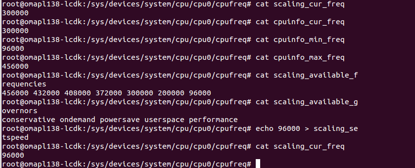
We have a custom OMAP L138 board.  We recently added support for adjusting the CPU speed from user space in Linux using /sys/devices/system/cpu/cpu0/cpufreq/scaling_setspeed.  Our device is a USB peripheral that is connected to a PC.  We are changing the ARM clock speed, and hence PLL0_SYSCLK2 as well which the USB peripheral runs from.  The USB PHY clock is generated from AUXCLK. 

The scenario is that after boot we will use cpufreq to lower the ARM clock speed.  The device is connected to the PC while booting.  Occasionally we will notice that the PC doesn't detect the device, and it won't detect the device until the device is disconnected and reconnected. 

When this happens I was seeing: "musb_g_ep0_irq 724: SetupEnd came in a wrong ep0stage in/status" in the kernel log.  So I started looking more closely at endpoint 0 processing.  What I found is that before the CPU frequency change, endpoint 0 transfers were occuring normally.  Then, shortly after we scale the CPU speed down, it looks like the endpoint 0 transfers are processed correctly except that after the driver sets DATAEND the controller never follows up with an interrupt in the status phase with csr = 0.  This stands out because up until the CPU clock speed changes, the USB controller seems to send a status interrupt with csr = 0 after every transfer.  After the CPU clock speed changes, this no longer happens.  Then once we disconnect and reconnect the device, we start seeing the interrupts again.  The time when the status interrupts are no longer occuring is also when we get the "SetupEnd" errors (mentioned above) as well. 

I can't be sure that it's the CPU scaling that's causing the problem but the problem appears to be occuring at about the time that the CPU frequency changes, and we weren't seeing this problem before those changes, so I'm making that assumption.  Does any of thise make any sense?  Is it possible that the USB controller is getting into a bad state that isn't cleared until the device is disconnected?  Is there any way that I can resolve this problem?

Thanks,


Brian

  • Hi Brian,

    We will try to look into it and get back.

    Regards,

    Shankari

  • If you are using cpu frequency scaling that requires USB to be operational while the PLL is running at a lower speed, please make sure you are not violating the min PLL requirement for USB to be operational.

    This is documented in the device datasheet

    Important Notice: The USB0 controller module clock (PLL0_SYSCLK2) must be greater than 30 MHz for
    proper operation of the USB controller. A clock rate of 60 MHz or greater is recommended to avoid data
    throughput reduction.

    While the note says throughput reduction, for reliable operations it best to ensure that PLL0_SYSCLK2 is above 30 MHz 

  • Thanks for the response.  When the clock speed is reduced PLL0_SYSCLK2 is running at 50 MHz.  Our device has been running correctly at that speed for several years.  We recently added support to run at a faster speed, and then reduce the clock back to our original speed when desired.  It seems that it is the act of reducing the clock speed that causes the USB controller to behave strangely.   

  • Ok, I understand what you might be saying:  Are you saying that when we bypass the PLL to set the new clock speed, PLLL0_SYSCLK2 is running below 30 MHz, and therefore the USB controller has undefined behavior?  Would that mean that I would have to use PLL1_SYSCLK3 as the bypass clock while I adjust PLL0?  I imagine that that code is not in the Linux cpufreq driver, so I would have to probably add that.  Or is there an accepted way to disable the USB controller in the Linux driver while the frequency change is taking place?

  • Hi Brian

    Sorry for the delayed resposne. 

    Brian Niebuhr said:
    Ok, I understand what you might be saying:  Are you saying that when we bypass the PLL to set the new clock speed, PLLL0_SYSCLK2 is running below 30 MHz, and therefore the USB controller has undefined behavior? 

    You got it. If the CPU frequency change involves changing the PLL multiplier, that requires you to take the PLL into bypass to change the frequency, for the time the PLL is in bypass, the USB module clock is operating at divide by 2 the oscin/clkin frequency. 

    PLL1_SYSCLK3 as an alternate input would be one way to handle this.

    Alternatively you can investigate if the CPU OPP you need , can be accomplished by just the PLL SYSCLK divider change alone, which does not require you to change to PLL to bypass mode (Section 8.2.2.4 in SPRUH77A) 

    I am not aware of native support available for this in our cpufreq driver but I could be wrong. 

    Regards

    Mukul

  • Hi Brian,

    We have done the following experiment to check whether the "OMAPL138 configured as USB peripheral" behave strangely when the ARM clock speed is changed.  Our result is "CPU scaling doesnot cause any problem in the USB peripheral (i.e., OMAPL138 configured as a device)

    Experimental steps:

    1. Configure the kernel of OMAPL138 to support USB 2.0 OTG. ( Enable the Host as well as the gadget side drivers. Here the the enabled gadget is "Ethernet gadget with CDC Ethernet Support.  Attached the .config file for reference.)

    2. Boot the built kernel and connect the OMAPL138 SDI EVM to the Linux host machine using the USB cable through USB 2.0 port.

    3. On linux host machine, Observe the message "Linux -USB Ethernet/RNDIS gadget" detected. ( using linux command : lsusb or dmesg )

    4. On linux host machine, observe a node created for usb0 for ethernet gadget ( linux command : ifconfig)

    5. In the target machine, change the CPU frequency using /sys/devices/system/cpu/cpu0/cpufreq/scaling_setspeed from 300MHz to 96MHz.

    6. Check whether on the host machine the device is still in connected state.

    7. Repeat the same test by changing all the available CPU frequencies.

    What is the current frequency and what is the frequency intended to change?

    Please share the error logs which encloses the bad state of the USB.

    What is the version of the Linux/Davinci PSP used?


    Regards,

    Shankari

    -------------------------------------------------------------------------------------------------------

    Please click the Verify Answer button on this post if it answers your question.
    --------------------------------------------------------------------------------------------------------

  • Hi Brian,

    When this happens I was seeing: "musb_g_ep0_irq 724: SetupEnd came in a wrong ep0stage in/status" in the kernel log.

    Have you enabled the USB DMA support ?

    This error seems to be you have disabled the USB CPPI DMA support in kernel.

    Could you please confirm this.

    make menuconfig ARCH=arm CROSS_COMPILE=arm-arago-linux-gnueabi-

    Device Drivers  --->

    [*] USB support  --->

    <*>     MUSB DMA mode (TI CPPI4.1)  --->

    [ ]     Disable DMA (always use PIO)

  • Yes, I have USB DMA support enabled as you have indicated.

  • Hi Brian,

    Thanks for your confirmation.

    What is the version of the Linux/Davinci PSP used?

    What is the frequency before and after "scaling_ setspeed" ?

  • Version 3.22.0.6

    Before: 372 MHz, After: 100 MHz

  • Hi Brian,

    Thanks for your details.

    I'm trying to reproduce your issue.

    I have used scripts to change various frequencies available in CPUfreq component (OPP)

    #!/bin/sh
    
    ping 10.100.1.143 &
    
    while true
    do
    echo "CPUFREQ test started..."
    echo 96000 > /sys/devices/system/cpu/cpu0/cpufreq/scaling_setspeed
    echo "Set 96MHz Done."
    sleep 60
    echo "SLEEP 1 over"
    echo 300000 > /sys/devices/system/cpu/cpu0/cpufreq/scaling_setspeed
    echo "Set 300MHz Done."
    sleep 60
    echo "SLEEP 2 over"
    echo 200000 > /sys/devices/system/cpu/cpu0/cpufreq/scaling_setspeed
    echo "Set 200MHz Done."
    sleep 60
    echo "SLEEP 3 over"
    echo 372000 > /sys/devices/system/cpu/cpu0/cpufreq/scaling_setspeed
    echo "Set 372MHz Done."
    sleep 60
    echo "SLEEP 4 over"
    echo 456000 > /sys/devices/system/cpu/cpu0/cpufreq/scaling_setspeed
    echo "Set 456MHz Done."
    sleep 60
    echo "SLEEP 5 over"
    echo 432000 > /sys/devices/system/cpu/cpu0/cpufreq/scaling_setspeed
    echo "Set 432MHz Done."
    sleep 60
    echo "SLEEP 6 over"
    echo 408000 > /sys/devices/system/cpu/cpu0/cpufreq/scaling_setspeed
    echo "Set 408MHz Done."
    sleep 60
    echo "SLEEP 7 over"
    echo "CPUFREQ test completed."
    done

    The "10.100.1.143" IP address got in my host machine through OMAPL138 CDC-gadget ethernet device.

    I ran the script to reproduce your issue for the whole day & night but I'm not getting any errors.

    I'm also using the same SDK "DaVinci-PSP-SDK-03.22.00.06"

  • Ok, thanks for testing this.  The test I'm running that's failing right now is to boot at 372 MHz with the USB cable attached and then lower the clock speed shortly after boot while the USB controller appears to still have some activity on ep0.  If I see no error, I reboot and try again.  It appears that if the frequency change comes at just the right time, the USB controller gets into a strange state.  Unplugging and replugging the USB cable while running your script might have a similar effect.

    I'm attempting a test right now where I disable the USB controller when changing the frequency.  I'll let you know if that has any effect. 


  • Hi Brian,

    I'm not facing any issues even I have initiated the PLL bypass mode (EXTCLKSRC bit is 1).

    The ARM is running at 100MHz while PLL is in bypass mode (EXTCLKSRC = 1; Use PLL1_SYSCLK3 for the PLL bypass clock)

    PLL0_SYSCLK2 = 50MHz ( measured at CLKOUT pin )

    If I set the bit EXTCLRSRC to '0' then I'm not able to ping "usb0" IP (USB gadget)  from board since the ARM is running at 24MHz which is not recommended for USB section and again it started to ping after I set '1' to "EXTCLRSRC" bit.

    musb_g_ep0_irq 724: SetupEnd came in a wrong ep0stage in/status

    After all the testing, We never come across the issue.

    Version 3.22.0.6

    Before: 372 MHz, After: 100 MHz

    root@omapl138-lcdk:/# cat /sys/devices/system/cpu/cpu0/cpufreq/scaling_available_frequencies 
    456000 432000 408000 372000 300000 200000 96000
    root@omapl138-lcdk:/#

    How did you configure 100MHz and why don't you try 96MHz as per OPP ?

    What is your reference clock frequency (OSCIN) ?

    24MHz ?

    Are you trying to initiate PLL bypass mode ?

    What is the value of PLLM, POSTDIV, PREDIV registers ?

    Please ensure that you have followed the chapter 8.2.2.3 & 8.2.2.4 for changing the frequency to 100MHz.

    I'm able to run the ARM at 100MHz only when I have initiated the PLL bypass mode with ECLKSRC bit is 1.

    We are not facing any problem when we configured the ARM at 96MHz & 100MHz (PLL bypass mode ).

    Could you please share the code which is used to configure the ARM at 100MHz ?

    Have you modified the Linux PSP in PLL section ?

    Do you have any TI EVM board ?

    Could you please try this experiment on your TI EVM and try reproduce the same USB behavior  ?

  • Hi Brian,

    Please answer the above questions.

    I have modified the "da850.c" file to add the OPP (operating performance point) entry for 100MHz.

    arch/arm/mach-davinci/da850.c

    /* Titus Debug : Added 100MHz */
    
    static const struct da850_opp da850_opp_100 = {
    	.freq		= 100000,
    	.prediv		= 2,
    	.mult		= 25,
    	.postdiv	= 3,
    	.cvdd_min	= 1000000,
    	.cvdd_max	= 1050000,
    };
    
    
    #define OPP(freq) 		\
    	{				\
    		.index = (unsigned int) &da850_opp_##freq,	\
    		.frequency = freq * 1000, \
    	}
    
    static struct cpufreq_frequency_table da850_freq_table[] = {
    	OPP(456),
    	OPP(432),
    	OPP(408),
    	OPP(372),
    	OPP(300),
    	OPP(200),
    	OPP(96),
    	OPP(100),	/* Titus Debug : Added 100MHz */
    	{
    		.index		= 0,
    		.frequency	= CPUFREQ_TABLE_END,
    	},
    };
    

    I have not faced any issues while setting the frequency from 372MHz to 100MHz.

    root@omapl138-lcdk:/sys/devices/system/cpu/cpu0/cpufreq# echo  372000 > scaling_setspeed
    root@omapl138-lcdk:/sys/devices/system/cpu/cpu0/cpufreq#
    root@omapl138-lcdk:/sys/devices/system/cpu/cpu0/cpufreq#
    root@omapl138-lcdk:/sys/devices/system/cpu/cpu0/cpufreq# echo 100000 > scaling_setspeed
    root@omapl138-lcdk:/sys/devices/system/cpu/cpu0/cpufreq#
    root@omapl138-lcdk:/sys/devices/system/cpu/cpu0/cpufreq#
    root@omapl138-lcdk:/sys/devices/system/cpu/cpu0/cpufreq# cat scaling_available_frequencies
    456000 432000 408000 372000 300000 200000 96000 100000
    root@omapl138-lcdk:/sys/devices/system/cpu/cpu0/cpufreq#
    root@omapl138-lcdk:/sys/devices/system/cpu/cpu0/cpufreq# cat scaling_cur_freq
    100000
    root@omapl138-lcdk:/sys/devices/system/cpu/cpu0/cpufreq#
    root@omapl138-lcdk:/sys/devices/system/cpu/cpu0/cpufreq#

  • How did you configure 100MHz and why don't you try 96MHz as per OPP ?

    I created another OPP with the same parameters you did in your next post.  We wanted the maximum performance we could get with 1.0V core, so we used 100 MHz instead of 96 MHz. 

    What is your reference clock frequency (OSCIN) ?

    24 MHz

    Are you trying to initiate PLL bypass mode ?

    No, we are not actually running in bypass mode.  We only enter bypass mode because it is required for the PLL frequency change (so we run at OSCIN until the PLL is reconfigured).  After the frequency is changed the PLL is engaged again.  This is not our custom code - we just used what's there in Linux.

    What is the value of PLLM, POSTDIV, PREDIV registers ?

    The same as you defined for your 100 MHz OPP.

    Please ensure that you have followed the chapter 8.2.2.3 & 8.2.2.4 for changing the frequency to 100MHz.

    We don't use custom code for this - it already exists.

    I'm able to run the ARM at 100MHz only when I have initiated the PLL bypass mode with ECLKSRC bit is 1.

    We are not facing any problem when we configured the ARM at 96MHz & 100MHz (PLL bypass mode ).

    I'm not sure I understand what you're saying.  Are you saying that you are switching to PLL1_SYSCLK3 to run at 96 or 100 MHz?  The cpufreq code in the PSP uses OSCIN as the bypass clock.  When the frequency changes, the PLL is bypassed (temporarily using OSCIN), the PLL frequency changes, and then the PLL is re-engaged.  Did you add additional code to set up PLL1_SYSCLK3 and then use that instead of PLL0 as the clock source?  I'm just using the standard code in the kernel, other than adding a 100 MHZ OPP.


    Could you please share the code which is used to configure the ARM at 100MHz ?

    I just added a 100 MHz OPP, like you did in your next post.

    Have you modified the Linux PSP in PLL section ?

    No.

    Do you have any TI EVM board ?

    Yes, we have a DA850 EVM

    Could you please try this experiment on your TI EVM and try reproduce the same USB behavior  ?

    I may if my hack doesn't work (see below).

    I have not faced any issues while setting the frequency from 372MHz to 100MHz.

    I think my problem may be limited to endpoint 0 processing.  From the description of your test, I don't know that you are exercising the endpoint 0 code.  Endpoint 0 is used for setup and configuration, but as far as I understand, not much happens on endpoint 0 after the device is initially connected.  So if your test is keeping the device connected, I'm not sure you will see the same behavior.  To reiterate my test setup:

    1. Start with the device power off and the USB connected to a PC

    2. Power up the device. 

    3. Shortly after boot, change the clock speed from 372 MHz to 100 MHz.  In my test, every time it fails there is still activity on endpoint 0 when the clock speed change occurs - probably due to the initial setup/configuration with the PC.

    4. If the test succeeds, I reboot the device and try again until it fails.

    You may be able to recreate these same conditions if you have a script looping on your EVM that alternates between 372 MHz and 100 MHz.  Then connect the USB cable and verify that your pings succeed.  If they succeed, disconnect the USB cable and reconnect (thus forcing more endpoint 0 communication).  As far as I can tell the clock speed change has to come at a specific point during the processing of the endpoint 0 transaction, because I often have to run my test hundreds of times before I see a failure.   

    My current theory is that if the clock speed change comes during a specific point in an endpoint 0 transaction, that transaction (or maybe several transactions?) fails.  I'm assuming that this causes the device to not get fully configured.  Because the device never got fully configured, the USB connection isn't active.  Once I disconnect and reconnect the device, the USB configuration starts over and succeeds, which makes the USB connection usable.

    The hack (and this definitely is a hack) that I'm currently testing is to disable the USB controller before changing the clock speed and then re-enable it after changing the clock speed.  In my initial test on Friday, I had completed an order of magnitude more successful iterations of my test when my battery died.  I am testing again today to see if I can get any failures.  The hack is as follows (when changing the frequency):

    1. Turn off the USB PHY.

    2. Turn off USB interrupts

    3. Turn off the USB20 module clock

    4. Change the frequency

    5. Turn on the USB PHY 

    6. Turn on the USB20 module clock

    7. Turn on USB interrupts

    As I said, that appears to be working, but it's a mess of a solution and I really don't know exactly why it's working.  Maybe someone who understands the USB controller better might be able to suggest a better solution. 

    The other thing I haven't tried is to use PLL1_SYSCLK3 as the bypass clock so the USB controller clock never drops below 30 MHz, which will maybe never cause the endpoint 0 transactions to fail.  That might be a cleaner solution, so I might have to try that.

    Is there anyone at TI that can tell me whether my hypothesis seems reasonable?  (That is:  the drop to OSCIN during the PLL frequency change is causing the USB controller to fail some endpoint 0 transations, which is causing the device to not be configured, which can only be fixed by disconnecting and reconnecting the device)

    Thanks for spending so much time looking into this.


  • Hi Brian,

    We only enter bypass mode because it is required for the PLL frequency change (so we run at OSCIN until the PLL is reconfigured).

    Please try to use clock from PLL1_SYSCLK3 while PLL freq changes.

    Did you add additional code to set up PLL1_SYSCLK3 and then use that instead of PLL0 as the clock source?

    No.

    Are you saying that you are switching to PLL1_SYSCLK3 to run at 96 or 100 MHz?

    Yes, Please try to change the clock source when you are trying to change PLL freq ( PLL bypass mode)

    Please check the below file for using the PLL1_SYSCLK3 for bypass clock.

    I have also not changed anything in Linux DaVinci-PSP-SDK-03.22.00.06,

    I will read your complete steps & workarounds and let me update our suggestions after discussed with our experts.

    < Linux DaVinci-PSP-SDK-03.22.00.06>/arch/arm/mach-davinci/da850.c


        /* Use PLL1_SYSCLK3 for the PLL0 bypass clock */
        da850_set_pll0_bypass_src(true);

    static void da850_set_pll0_bypass_src(bool pll1_sysclk3)
    {
        struct clk *clk = &pll0_clk;
        struct pll_data *pll;
        unsigned int v;

        pll = clk->pll_data;
        v = __raw_readl(pll->base + PLLCTL);
        if (pll1_sysclk3)
            v |= PLLC0_PLL1_SYSCLK3_EXTCLKSRC;
        else
            v &= ~PLLC0_PLL1_SYSCLK3_EXTCLKSRC;
        __raw_writel(v, pll->base + PLLCTL);


    }

  • Yes, Please try to change the clock source when you are trying to change PLL freq ( PLL bypass mode)

    Please check the below file for using the PLL1_SYSCLK3 for bypass clock.

    Ok, I'll try making this change and retest.

  • Hi Brian,

    Thanks.

    Please update us after completed your testing.

    I have checked all our released TI PSP versions including latest SDK (MCSDK), I didn't see code for setting the EXTCLKSRC bit to '0' in anywhere.

    mcsdk_1_01_00_01/board-support/linux-3.3-psp03.22.00.06.sdk

    mcsdk_1_01_00_02/board-support/linux-3.3-psp03.22.00.06.sdk

    Could you please read the value of PLLC0_CTL register

    static void da850_set_pll0_bypass_src(bool pll1_sysclk3)
    {
    	struct clk *clk = &pll0_clk;
    	struct pll_data *pll;
    	unsigned int v;
    
    	pll = clk->pll_data;
    	v = __raw_readl(pll->base + PLLCTL);
    	if (pll1_sysclk3)
    		v |= PLLC0_PLL1_SYSCLK3_EXTCLKSRC;
    	else
    		v &= ~PLLC0_PLL1_SYSCLK3_EXTCLKSRC;
    	__raw_writel(v, pll->base + PLLCTL);
    
    	/* Titus Debug : print the PLLC0_CTL register */
    	printk("PLL0_CTL register %p\n",v)
    
    }

  • I have checked all our released TI PSP versions including latest SDK (MCSDK), I didn't see code for setting the EXTCLKSRC bit to '0' in anywhere.

    You are right.  I went back and checked, and we switched to using OSCIN as the bypass clock on our board a long time ago because we had disabled PLL1_SYSCLK3 since we didn't need it.  I have reverted that change and I'll continue testing.  Hopefully that will fix the issue.

  • Hi Brian,

    Thanks for your update.

    Please let us know the results.

  • After my initial testing, it appears that using PLL1_SYSCLK3 as the bypass clock has fixed the problem.  I'll mark your answer as verified.  I appreciate the help.

  • Hi Brian,

    Sounds good.

    We are glad that your problem got fixed.

    Thanks for your update.