This thread has been locked.

If you have a related question, please click the "Ask a related question" button in the top right corner. The newly created question will be automatically linked to this question.

EDMA3 LLD request channel for link fails

I would need to perform 17 dma channel transfers with their respective 34 link and 34 chain channel settings.

After requesting the 24th channel for link, EDMA3_DRV_requestChannel function returns -162

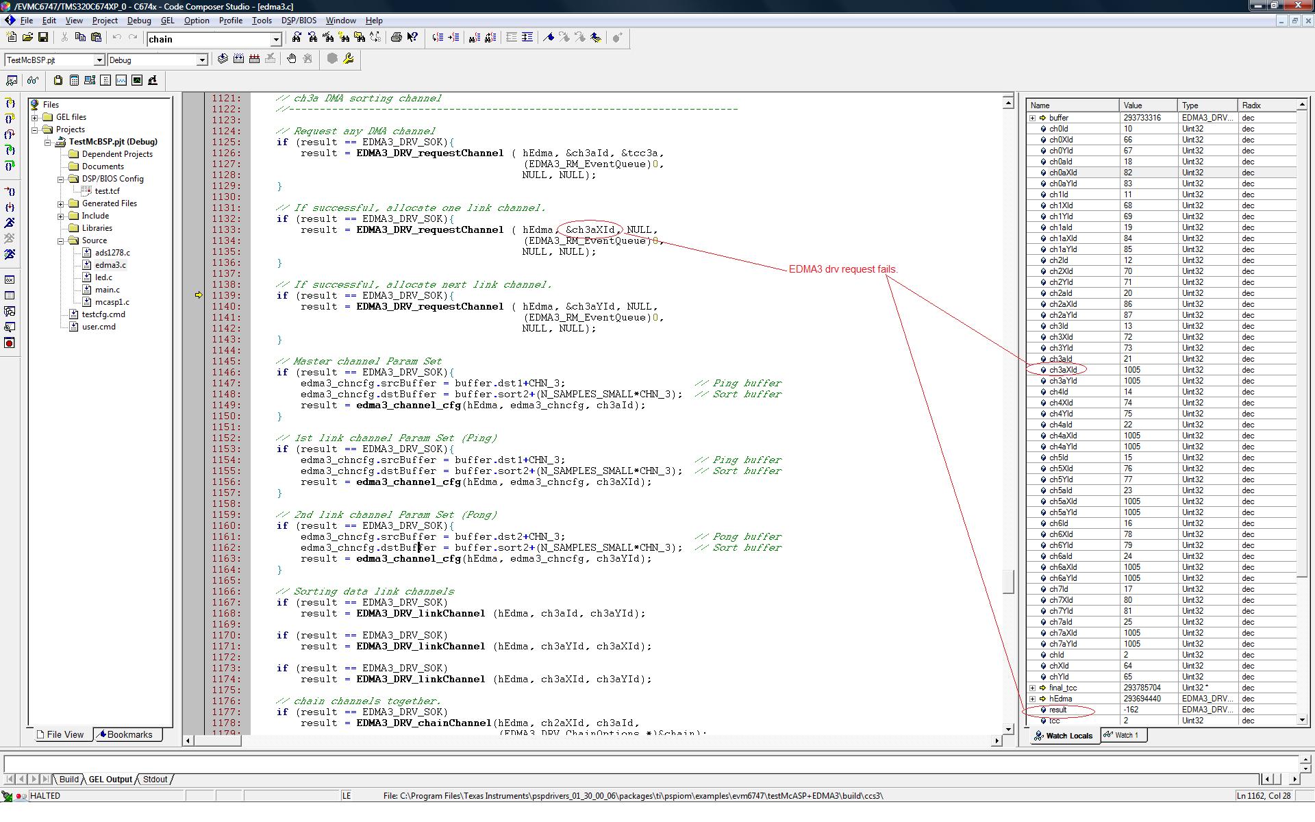
What could be wrong whit this? I use C6747 platform and edma3_lld_01_11_00_03 version

Thanks in advance,

Gaston

  • With the C6747 EDMA3, you get

    • 32 DMA channels that are associated with external events or can be triggered by chaining or by manual triggering
    • 8 QDMA channels
    • 128 PaRAM sets

    The first 32 PaRAM sets are dedicated to the 32 DMA channels. However, if a particular DMA channel is not being used, the associated PaRAM set may be used as a link set or for QDMA.

    Not being an expert user on the LLD, I am not sure how you are supposed to find the error name for a given error code. You have called the function correctly, and have identified the error code as -162 (decimal). The only way I know to find the error code is to use a desktop search tool that can find a given error code. I went searching for a known error symbol, EDMA3_DRV_E_INVALID_PARAM, and found it in edma3_drv.h. This showed me that the EDMA3_DRV_E_xxx error codes start at EDMA3_DRV_E_BASE = -128 and count down from there, but they do not go far enough to reach -162 (-34). So I figured since we have some DRV symbols and some RM symbols, I searched for EDMA3_RM_E_BASE. That showed up in edma3_rm.h with a value of -155, so I only needed to count down by -7 to get to -162. This led me to the symbol
    EDMA3_RM_E_ALL_RES_NOT_AVAILABLE with the comment /** No Resource of specified type is available */. So this is the error response from your call to EDMA3_DRV_requestChannel, saying that the resource you want is not available.

    You are asking for a Link PaRAM set (it really should not be called a channel, but that is how the LLD labels it), and it would appear that there are not any left. The comment in edma3_drv.h for EDMA3_DRV_LINK_CHANNEL is

    edma3_drv.h said:
    /**
     * Used to specify any available PaRAM Set while requesting
     * one. Used in the API EDMA3_DRV_requestChannel(), for Link channels.
     * PaRAM Set from the pool of (owned && non_reserved && available_right_now)
     * PaRAM Sets will be chosen and returned.
     */

    There could be issues with the default allocation of PaRAM sets for your code to "own", or with shadow regions, or you have simply run out of PaRAM sets to use.

    Gaston said:
    I would need to perform 17 dma channel transfers with their respective 34 link and 34 chain channel settings.

    "34 chain channel settings" does not make sense to me. Please explain what you are trying to do. The 2x numbers lead me to guess you are using ping-pong buffers, but the chaining is not obvious, yet. And the chain channel settings term is confusing to me.

  • RandyP said:
    EDMA3_RM_E_ALL_RES_NOT_AVAILABLE with the comment /** No Resource of specified type is available */. So this is the error response from your call to EDMA3_DRV_requestChannel, saying that the resource you want is not available.

    Ok, it seems there is one base symbol for DRV (-128) and another for the RM module (-155). Now this is clear to me.

    RandyP said:
    You are asking for a Link PaRAM set (it really should not be called a channel, but that is how the LLD labels it), and it would appear that there are not any left. The comment in edma3_drv.h for EDMA3_DRV_LINK_CHANNEL is

    If LLD function calling is not entirely accurate, how should it be?

    RandyP said:
    There could be issues with the default allocation of PaRAM sets for your code to "own", or with shadow regions, or you have simply run out of PaRAM sets to use.

    All right I will try to find out more on LLD documentation (quite extensive, by the way)

    RandyP said:
    "34 chain channel settings" does not make sense to me. Please explain what you are trying to do. The 2x numbers lead me to guess you are using ping-pong buffers, but the chaining is not obvious, yet. And the chain channel settings term is confusing to me.

    Yes indeed, I use ping-pong buffers for every DMA channel and I need 17 DMA channels. Hence this is the way I use 34 link PSets (not link channels) but I will try to explain what I want to do.

    1. 1 DMA channel for McASP acquisition using 8 serializers. Ping-pong is implemented in this case. Then I have 1 DMA chn and 2 link PSets
    2. Samples are acquired unsorted (smpl0_ch0, smpl0_chn1,..,smpl0_ch7,...,smplN_ch0, smplN_chn1,...,smplN_ch7) so I have to sort them. I do not want to waiting for a bPingPong flag to process the buffers. Rather, I chain DMA channel to a sort data channel (mem-to-mem transfer). As I have to sort both ping and pong buffers It is necessary to chain the transfer at the end of the ping and also at the end of the pong. So I have 1 DMA chn for data sorting, 2 link Psets and 2 chain PSets.
    3. Due to the large number of samples to process I have to split sorting data into 8 fragments to be within the range of PaRAM counters. This leads to 8 DMA chn for data sorting and 16 link PSets and 16 chain PSets
    4. Moreover I need to perform a downsampling maintaining the original buffer. This means I have to repeat the from point 2 (with a downsampling data sort). This leads to extra 8 DMA chn for data sorting and 16 link PSets and 16 chain PSets.

    In short:

    • 17 DMA chn (1 for McASP service, 8 for data sorting and 8 for downsampling mem-to-mem transfer)
    • 34 link PSets (2 for McASP, 16 for data sorting and 16 for downsampling mem-to-mem transfer)
    • 34 chain PSets (2 for McASP, 16 for data sorting and 16 for downsampling mem-to-mem transfer)

    I hope this explanation helps us understand the problem and here is the first channels config:

        //-------------------------------------------------------------------------
        // McASP1 DMA channel
        //-------------------------------------------------------------------------

        edma3_chncfg.srcBuffer = buffer.src;            // Source address
        edma3_chncfg.dstBuffer = buffer.dst1;            // Destination buffer address
        edma3_chncfg.srcbidx = 0;                        //
        edma3_chncfg.srccidx = 0;                        //
        edma3_chncfg.desbidx = 4;                        // 32-bit word
        edma3_chncfg.descidx = 32;                        // 8 Serielizers (32-bit word per serializer)
        edma3_chncfg.acnt = 4;                            // 32-bit word
        edma3_chncfg.bcnt = 8;                            // 8 Serializers
        edma3_chncfg.ccnt = 10240;                        // Samples per serializer
        edma3_chncfg.sync = EDMA3_DRV_SYNC_AB;            // AB sync
        edma3_chncfg.BRCnt = edma3_chncfg.bcnt;            // Set B count reload as B count.

        // Intermediate completion is for all TRs of a transfer EXCEPT the LAST.
        // Final TCC is for only the LAST TR of a transfer
        edma3_chncfg.tcomplete = 0u;                    // Transfer complete disabled
        edma3_chncfg.itcomplete = 0u;                    // Intermediate transfer complete disabled
        edma3_chncfg.tchcomplete = 0u;
        edma3_chncfg.itchcomplete = 0u;

        // Request any DMA channel
        if (result == EDMA3_DRV_SOK){
            result = EDMA3_DRV_requestChannel (    hEdma, &chId, &tcc,
                                                (EDMA3_RM_EventQueue)1,
                                                NULL, NULL);
        }

        // If successful, allocate one link channel.
        if (result == EDMA3_DRV_SOK){
            result = EDMA3_DRV_requestChannel (    hEdma, &chXId, NULL,
                                                (EDMA3_RM_EventQueue)1,
                                                NULL, NULL);
        }

        // If successful, allocate next link channel.
        if (result == EDMA3_DRV_SOK){
            result = EDMA3_DRV_requestChannel (    hEdma, &chYId, NULL,
                                                (EDMA3_RM_EventQueue)1,
                                                NULL, NULL);
        }
       
        // Master DMA channel Param Set
        if (result == EDMA3_DRV_SOK)
            result = edma3_channel_cfg(hEdma, edma3_chncfg, chId);

        // 1st link channel Param Set (Ping)
        if (result == EDMA3_DRV_SOK)
            result = edma3_channel_cfg(hEdma, edma3_chncfg, chXId);

        // 2nd link channel Param Set (Pong)
        if (result == EDMA3_DRV_SOK){
            edma3_chncfg.dstBuffer = buffer.dst2;
            result = edma3_channel_cfg(hEdma, edma3_chncfg, chYId);
        }

        // Link main channels
        if (result == EDMA3_DRV_SOK)
            result = EDMA3_DRV_linkChannel (hEdma, chId, chYId);

        if (result == EDMA3_DRV_SOK)
            result = EDMA3_DRV_linkChannel (hEdma, chYId, chXId);

        if (result == EDMA3_DRV_SOK)
            result = EDMA3_DRV_linkChannel (hEdma, chXId, chYId);

        //-------------------------------------------------------------------------
        // ch0 DMA sorting channel
        //-------------------------------------------------------------------------

        // chain config
        chain.tcintEn =        EDMA3_DRV_TCINTEN_DIS;        // Transfer complete interrupt is disabled
        chain.itcintEn =     EDMA3_DRV_ITCINTEN_DIS;        // Intermediate transfer complete interrupt is disabled
        chain.tcchEn =         EDMA3_DRV_TCCHEN_EN;        // Transfer complete chaining enable
        chain.itcchEn =     EDMA3_DRV_ITCCHEN_DIS;        // Intermediate transfer complete chaining disable

        edma3_chncfg.tcomplete =     0u;
        edma3_chncfg.itcomplete =     0u;
        edma3_chncfg.tchcomplete =     1u;
        edma3_chncfg.itchcomplete =    0u;

        edma3_chncfg.srcbidx = 32u;                        //
        edma3_chncfg.srccidx = 0u;                        //
        edma3_chncfg.desbidx = 4u;                        // 32-bit word
        edma3_chncfg.descidx = 0u;                        //
        edma3_chncfg.acnt = 4u;                            // 32-bit word
        edma3_chncfg.bcnt = 10240u;                        //
        edma3_chncfg.ccnt = 1u;                            //
        edma3_chncfg.sync = EDMA3_DRV_SYNC_AB;            // AB sync
        edma3_chncfg.BRCnt = edma3_chncfg.bcnt;            //

        // Request any DMA channel
        if (result == EDMA3_DRV_SOK){
            result = EDMA3_DRV_requestChannel (    hEdma, &ch0Id, &tcc0,
                                                (EDMA3_RM_EventQueue)0,
                                                NULL, NULL);
        }

        // If successful, allocate one link channel.
        if (result == EDMA3_DRV_SOK){
            result = EDMA3_DRV_requestChannel (    hEdma, &ch0XId, NULL,
                                                (EDMA3_RM_EventQueue)0,
                                                NULL, NULL);
        }

        // If successful, allocate next link channel.
        if (result == EDMA3_DRV_SOK){
            result = EDMA3_DRV_requestChannel (    hEdma, &ch0YId, NULL,
                                                (EDMA3_RM_EventQueue)0,
                                                NULL, NULL);
        }

        // Master channel Param Set
        if (result == EDMA3_DRV_SOK){
            edma3_chncfg.srcBuffer = buffer.dst1+CHN_0;                        // Ping buffer
            edma3_chncfg.dstBuffer = buffer.sort1+(N_SAMPLES_LARGE*CHN_0);    // Sort buffer
            result = edma3_channel_cfg(hEdma, edma3_chncfg, ch0Id);
        }

        // 1st link channel Param Set (Ping)
        if (result == EDMA3_DRV_SOK){
            edma3_chncfg.srcBuffer = buffer.dst1+CHN_0;                        // Ping buffer
            edma3_chncfg.dstBuffer = buffer.sort1+(N_SAMPLES_LARGE*CHN_0);    // Sort buffer
            result = edma3_channel_cfg(hEdma, edma3_chncfg, ch0XId);
        }

        // 2nd link channel Param Set (Pong)
        if (result == EDMA3_DRV_SOK){
            edma3_chncfg.srcBuffer = buffer.dst2+CHN_0;                        // Pong buffer
            edma3_chncfg.dstBuffer = buffer.sort2+(N_SAMPLES_LARGE*CHN_0);    // Sort buffer
            result = edma3_channel_cfg(hEdma, edma3_chncfg, ch0YId);
        }

        // Sorting data link channels
        if (result == EDMA3_DRV_SOK)
            result = EDMA3_DRV_linkChannel (hEdma, ch0Id, ch0YId);

        if (result == EDMA3_DRV_SOK)
            result = EDMA3_DRV_linkChannel (hEdma, ch0YId, ch0XId);

        if (result == EDMA3_DRV_SOK)
            result = EDMA3_DRV_linkChannel (hEdma, ch0XId, ch0YId);

       
        // chain channels together.
        if (result == EDMA3_DRV_SOK)
            result = EDMA3_DRV_chainChannel(hEdma, chXId, ch0Id,
                                               (EDMA3_DRV_ChainOptions *)&chain);
       
        if (result == EDMA3_DRV_SOK)
            result = EDMA3_DRV_chainChannel(hEdma, chYId, ch0Id,
                                               (EDMA3_DRV_ChainOptions *)&chain);
       
        //-------------------------------------------------------------------------
        // ch1 DMA sorting channel
        //-------------------------------------------------------------------------

        // Request any DMA channel
        if (result == EDMA3_DRV_SOK){
            result = EDMA3_DRV_requestChannel (    hEdma, &ch1Id, &tcc1,
                                                (EDMA3_RM_EventQueue)0,
                                                NULL, NULL);
        }

        // If successful, allocate one link channel.
        if (result == EDMA3_DRV_SOK){
            result = EDMA3_DRV_requestChannel (    hEdma, &ch1XId, NULL,
                                                (EDMA3_RM_EventQueue)0,
                                                NULL, NULL);
        }

        // If successful, allocate next link channel.
        if (result == EDMA3_DRV_SOK){
            result = EDMA3_DRV_requestChannel (    hEdma, &ch1YId, NULL,
                                                (EDMA3_RM_EventQueue)0,
                                                NULL, NULL);
        }

        // Master channel Param Set
        if (result == EDMA3_DRV_SOK){
            edma3_chncfg.srcBuffer = buffer.dst1+CHN_1;                        // Ping buffer
            edma3_chncfg.dstBuffer = buffer.sort1+(N_SAMPLES_LARGE*CHN_1);    // Sort buffer
            result = edma3_channel_cfg(hEdma, edma3_chncfg, ch1Id);
        }

        // 1st link channel Param Set (Ping)
        if (result == EDMA3_DRV_SOK){
            edma3_chncfg.srcBuffer = buffer.dst1+CHN_1;                        // Ping buffer
            edma3_chncfg.dstBuffer = buffer.sort1+(N_SAMPLES_LARGE*CHN_1);    // Sort buffer
            result = edma3_channel_cfg(hEdma, edma3_chncfg, ch1XId);
        }

        // 2nd link channel Param Set (Pong)
        if (result == EDMA3_DRV_SOK){
            edma3_chncfg.srcBuffer = buffer.dst2+CHN_1;                        // Pong buffer
            edma3_chncfg.dstBuffer = buffer.sort2+(N_SAMPLES_LARGE*CHN_1);    // Sort buffer
            result = edma3_channel_cfg(hEdma, edma3_chncfg, ch1YId);
        }

        // Sorting data link channels
        if (result == EDMA3_DRV_SOK)
            result = EDMA3_DRV_linkChannel (hEdma, ch1Id, ch1YId);

        if (result == EDMA3_DRV_SOK)
            result = EDMA3_DRV_linkChannel (hEdma, ch1YId, ch1XId);

        if (result == EDMA3_DRV_SOK)
            result = EDMA3_DRV_linkChannel (hEdma, ch1XId, ch1YId);

        // chain channels together.
        if (result == EDMA3_DRV_SOK)
            result = EDMA3_DRV_chainChannel(hEdma, ch0XId, ch1Id,
                                               (EDMA3_DRV_ChainOptions *)&chain);
       
        if (result == EDMA3_DRV_SOK)
            result = EDMA3_DRV_chainChannel(hEdma, ch0YId, ch1Id,
                                               (EDMA3_DRV_ChainOptions *)&chain);

  • Gaston said:
    If LLD function calling is not entirely accurate, how should it be?

    You are writing it correctly, based on the symbols and labels used in the LLD. I was just complaining about the naming conventions that the LLD uses. But you have to use their naming conventions to use the LLD. I apologize for the confusion and for complaining about something neither of us can change.

    RandyP said:
    There could be issues with the default allocation of PaRAM sets for your code to "own", or with shadow regions, or you have simply run out of PaRAM sets to use.

    Here is a bit of a helping nudge to find the likely problem. At some point, your code calls EDMA3_RM_open(). The second argument is of type (EDMA3_RM_Param *) and is likely to be called initParam, since it is called that in bios_edma3_rm_sample_init.c. One of the member of this argument is initParam.rmInstInitConfig which is likely to be set to the address of the default config struct sampleInstInitConfig, since it is in bios_edma3_rm_sample_init.c. In the file bios_edma3_rm_sample_c6747_cfg.c, this default config struct is defined and filled with default values.

    Even though you only have 1 core in the C6747, the sample code uses Region 1 because of the way some of the internal wiring connections are made. Region 1 is convenient to use. But even though there is only 1 core being used and only 1 region being used, only PaRAM sets 55-0 and DMA channels 31-0 and QDMA channels 3-0 and TCCs 31-0 are assigned to Region 1 in the default in that file.

    It makes more sense to you and me to take them all. So you can create your own myInstInitConfig struct by copying the sample one to your own source files and changing the allocations. You may want to make changes for the resources owned and the resources reserved. See the EDMA3_RM_User_Guide and search for EDMA3_RM_InstanceInitConfig to find a good explanation of the different parameters and what "owned" and "reserved" mean.

    Gaston said:
    Yes indeed, I use ping-pong buffers for every DMA channel and I need ...

    Let me see if I am starting to understand what you are doing with the McASP data. Tell me if this is correct in terms of data movement and data storage:

    1. You have allocated a BIG buffer that is 10240 x 8 words to hold all eight McASP samples in a ping buffer, and a second identical one for the BIG pong buffer.
    2. You also have 8 Small buffers that are 10240 x 1 word to separately hold the sorted data from each of the serializers in ping buffers, and 8 more identical ones for the Small pong buffers.
    3. When a McASP event occurs, you want to copy 8 samples to the next available spaces in one of the BIG buffers.
    4. Once 10240 McASP events have occured and the ping buffer is full, you want to sort the separate serializer data to the 8 Small buffers.
    5. Then you will start processing on those 8 Small buffers and the next 10240 McASP events will send data to the pong buffers, BIG and then 8 x Small.

    How close is the above list to how you want data to move around?

    If you can help me understand, I think I can help you cut down the EDMA3 resource requirements a lot. If you can reduce the depth of your buffers from 10240 to 2340 or less, it could get very easy, even if you need more than 2 ping/pong buffers.


    On another thread, I discussed a way to do channel sorting from a McASP using a different DMA channel for each of the serializers.

  • RandyP said:
    It makes more sense to you and me to take them all. So you can create your own myInstInitConfig struct by copying the sample one to your own source files and changing the allocations. You may want to make changes for the resources owned and the resources reserved. See the EDMA3_RM_User_Guide and search for EDMA3_RM_InstanceInitConfig to find a good explanation of the different parameters and what "owned" and "reserved" mean.

    Well, I modified InstInitConfig struct in order to get more own PaRAMSets. I found there is the same structure in RM and DRV modules and I do not know the cause of such duplicity. Anyway, I increased the value of 55 to 96 and now edma3 request functions works with no errors.

    RandyP said:
    Let me see if I am starting to understand what you are doing with the McASP data. Tell me if this is correct in terms of data movement and data storage:

    Thank you Randy, I very much appreciate your willingness to help.

    RandyP said:
    You have allocated a BIG buffer that is 10240 x 8 words to hold all eight McASP samples in a ping buffer, and a second identical one for the BIG pong buffer.

    Right.

    RandyP said:
    You also have 8 Small buffers that are 10240 x 1 word to separately hold the sorted data from each of the serializers in ping buffers, and 8 more identical ones for the Small pong buffers.

    Well, the group of 8 buffers of 10240 x 1 holding the sorted data is unique. In this case Ping and Pong buffer destination addresses are the same.

    RandyP said:
    When a McASP event occurs, you want to copy 8 samples to the next available spaces in one of the BIG buffers.

    RandyP said:
    Once 10240 McASP events have occured and the ping buffer is full, you want to sort the separate serializer data to the 8 Small buffers.

    I am not sure about you say at point 3. I am waiting for 10240 x 8 McASP events and when ping buffer is full I sort the data into 8 Small buffers.

    RandyP said:
    Then you will start processing on those 8 Small buffers and the next 10240 McASP events will send data to the pong buffers, BIG and then 8 x Small.


    It is correct but I wait for 81920 McASP events instead 10240.

    I believe you are really close to understand what I want to do.

    RandyP said:
    If you can help me understand, I think I can help you cut down the EDMA3 resource requirements a lot. If you can reduce the depth of your buffers from 10240 to 2340 or less, it could get very easy, even if you need more than 2 ping/pong buffers.


    I think so. I probably chose the wrong path and should to consider another approach. Maybe the thread that you mentioned could be fine to start.

  • It is my understanding that a single McASP event indicates that all 8 serializers have data available. Your current programming of the primary capture channel copies all 8 words in response to that single McASP event. So I was making a distinction between McASP events and the number of words that are stored.

    I think I understand your data flow requirements, and based on that here are the design steps I would follow:

    1. Data space requirements: 8 10240x1W buffers for processing + time-delay buffer to capture new data while processing old data (2 10240x8W ping-pong buffers chosen)
    2. One event-driven DMA channel (call it M) to copy 8 words per event into a ping or pong buffer, with 2 Link PSets to switch between ping and pong at completion.
    3. When Channel M completes, it will chain to start data sorting, let's call it Channel A. Of course, Channel M links in its pong PSet so Channel M will start storing to the pong buffer.
    4. Data sorting plan 1: Channel A copies all of the first serializer's data to the first 10240x1W, then chains to Channel B and links in a new PSet for the pong set later. Channel A might also generate an interrupt if you want to start processing as soon as the new data is available. Channel B copies the next serializer and chains to C, and so on. Each sorting channel needs a pair of Link PSets so it can copy from ping or pong. You can generate a unique interrupt after each serializer's data has been copied or just at the end after Channel H is finished.
    5. Data sorting plan 2: Channel A copies all of the first serializer's data (ACNT=4, BCNT=10240, SyncDim=ABSync) to the first 10240x1W, then chains to itself using TCC="A". With CCNT=8 and SrcCidx=4 and DstBidx=4*10240, this single channel can do all of the sorting as long as the 8 buffers are contiguous. There will need to be 2 Link PSets for Channel A to switch it between ping and pong source addresses. You can generate an interrupt after each serializer's data has been copied or at the end after all of them have been copied, but it will be the same interrupt TCC for each. Remember to set OPT.ITCCHEN=1 and OPT.TCCHEN=0.
    6. The resource requirements for data sorting plan 1 are: 1 Channel M + 2 Link PSets + 8 Channels A-H + 16 Link PSets. Each channel also includes an active PSet.
    7. The resource requirements for data sorting plan 2 are: 1 Channel M + 2 Link PSets + 1 Channels A + 2 Link PSets. Each channel also includes an active PSet.
  • RandyP said:
    It is my understanding that a single McASP event indicates that all 8 serializers have data available. Your current programming of the primary capture channel copies all 8 words in response to that single McASP event. So I was making a distinction between McASP events and the number of words that are stored.

    Yes, I was confused, Moreover since I use AB-sync transfer type, McASP event triggers a two­dimensional transfer of BCNT arrays of ACNT bytes (A*B) .

    Plan 2 could be fine but DstBidx=4*10240 is out of range (-32768, 32767). I continue thinking.