This thread has been locked.

If you have a related question, please click the "Ask a related question" button in the top right corner. The newly created question will be automatically linked to this question.

EMIF register configuration for TMS320C6202


We have a legacy DSP board that uses a bunch of TI TMS320C 6202 GJL chips.  Each DSP has two 16-bit SDRAMs attached to it.

This board has been shipping for nearly 10 years now, and the SDRAM we use is going EOL.

We currently use an ISSI 42S16100C1.  This is a 512K Words x 16 Bits x 2 Banks SDRAM (16 Mb).

We replaced a board with the new rev of the ISSI part - IS42S16100E (same memory arrangement and density).

After we replaced some old parts with new ones on a board, the board stopped working - has data errors.

I found that there are 7 registers in the chip for the EMIF interface for the 6202 (page 27 of the " TMS320C6000 EMIF-to-External SDRAM Interface" application note SPRA433E - September 2007).  We currently configure these as follows:

GBLCTL = 0x0000 3040

CE1CTL - N/A, we use CE2 for both SDRAMs

CE0CTL - N/A, we use CE2 for both SDRAMs

CE2CTL - 0x0000 0030

CE3CTL - N/A, we use CE2 for both SDRAMs

SDCTL = 0x0732 A000

DTIM = 0x0000 1F40


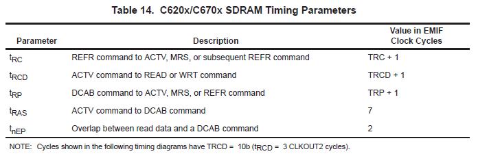
This means that for SDRAM Control:

-TRC = 10d

-TRP = 2d

-TRCD = 3d

-SWID = 1  (not sure if this is correct)

And for SDRAM Timing:

-Counter = 1d

-Period = 3904d


For the DRAM Timing parameters:

                        OLD rev C1    NEW rev E

TRC                     54 ns              54 ns

TRP                     18 ns              18 ns

TRCD                   16 ns              18 ns

Refresh Time   64 ms             32 ms
Cycles              (4096)              (2048)
TDPL                   1 CLK              2 CLK
TDAL              1 CLK + TRP       2 CLK + TRP
Also it seems all the setup times used to be 1.5ns and now they are 2ns.
Are the original register settings correct?  It works anyway with the OLD rev C1.  However, with the NEW rev E and the slight differences in timing parameters, it does not work.  What should the new register settings be?

  • One thing to remember in your calculations is that the value in the register is N-1. So for Trc where the value in the register is 0xA or 10d, the actual timing parameter is 11.

    You then multiply the actual timing number times the EMIF clock period to get the time in ns that is provided by that register setting.

    For refresh calculations, you will need to look at the SDRAM datasheet to understand whether they need the refresh handled differently. The available time for refreshes is cut in half but the number of cycles required is also cut in half. So you may be okay on the refresh timer value.

    The documents you will want to reference are

    I did not find DPL or DAL in these documents.

    Since your memory setup time is worse, you will need to do detailed board timing analysis to make sure this new memory is compatible with the C6202.

  • I am aware of the formulas, the datasheets, and the app note.

    Can you please tell me if and how tDAL and tDPL are adjustable in the registers.

    The SDRAM that we were using that worked had    tDPL = 1 CLK   and   tDAL = 1 CLK + tRP

    The new SDRAM that we tried on the board and doesn't work has    tDPL =2 CLK   and   tDAL = 2 CLK + tRP

    We cannot find any SDRAMs still available that have a 1-CLK tDAL and tDPL.  All of them have gone EOL.  All of the current SDRAMs has a 2-CLK tDAL and tDPL.
    Is there any way around this?  Can this be changed in code so that the SDRAM controller in the DSP can use a SDRAM with a 2-CLK tDPL and tDAL?
    Thanks

  • The following table lists the programmable and fixed parameters available for the C620x family of DSPs. Newer DSPs have more parameters that can be configured.

    What DSP clock speed and CLKOUT2 speed are you running?

    How much delay do you measure currently for tDPL and tDAL when you observe the timing on a scope or logic analyzer?

    If you increase tRP, what change do you see in tDPL and tDAL?