


Hi,
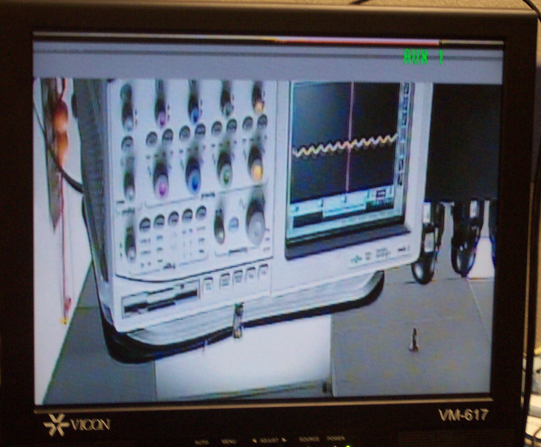
I am trying to interface a camera module to the DM365 based custom hardware. I am trying to run the loopback test that comes with DM365 test projects.
Information about my camera module:
Output: YCbCr-BT.601 16 bit , progressive
Cam Clock: 36MHz
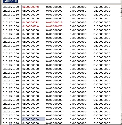
I modified the VPFE and VPBE register settings as below.
/*VPFE setings*/
width = 1280;
height =720;
ISIF_SYNCEN = 0x0000; // Disable VPFE during setup
ISIF_MODESET = 0x1004; // Progressive, NOT Interlaced
// VD polarity as negative
// HD polarity as positive - this avoids clock offset value
// HD and VD are inputs to ISIF
ISIF_HDW = 0x0000; // not needed if HD is input
ISIF_VDW = 0x0000; // not needed if VD is input
ISIF_PPLN = 0x0500; // 1280
ISIF_LPFR = 0x02D0; // 720
ISIF_SPH = 0x0000; // start pixel horizontal, this can be zero if HD polarity is positive
ISIF_LNH = width; // * Horizontal lines
ISIF_HSIZE = width >> 4; // Horizontal line offset - test 2/23/10
ISIF_SLV0 = 0x0000; // Vertical start line - field 0 - n/a
ISIF_SLV1 = 0x0000; // Vertical start line - field 1 - n/a
ISIF_LNV = height; // Vertical lines
ISIF_CULH = 0xffff; // Disable horizontal culling
ISIF_CULV = 0x00ff; // Disable vertical culling
/*
* Interleave the two fields
*/
ISIF_SDOFST = 0x0249; // Line offset - test ? - applies for interlaced fields - n/a
ISIF_CADU = 0x0400; // Frame buffer address high
ISIF_CADL = 0x0000; // Frame buffer address low
ISIF_REC656IF = 0x0000; // REC656 disabled
/*
* Input format is Cb:Y:Cr:Y, w/ Y in odd-pixel position
*/
ISIF_CCDCFG = 0x0800; // CCD configuration
ISIF_FMTCFG = 0x0000; // Disable formatter
ISIF_FMTSPH = 0x0000;
ISIF_FMTLNH = 0x0500; // test - ? - spec states that this is a reserved register
ISIF_FMTSLV = 0x0000;
ISIF_FMTLNV = 0x0000;
ISIF_SYNCEN = 0x0003; // Enable CCDC
}
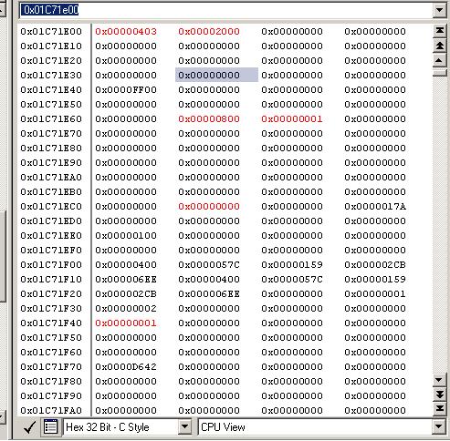
/*VPBE settings*/
basep_x = 122;
basep_y = 18;
width = 1280;//720;
height = 720;//480;
/*
* Setup clocking / DACs
*/
VDAC_CONFIG = 0x081141CC;//0x081141CF; // Take DACs out of power down mode
VPSS_CLKCTL = 0x00000018; // Enable DAC and VENC clock, both at 27 MHz
VPSS_VPBE_CLK_CTRL = 0x00000011; // Select enc_clk*1, turn on VPBE clk
VENC_CLKCTL = 0x00000001; // Enable venc & digital LCD clock
/*
* Setup OSD
*/
OSD_MODE = 0x000000fc; // Blackground color blue using clut in ROM0
OSD_OSDWIN0MD = 0; // Disable both osd windows and cursor window
OSD_OSDWIN1MD = 0;
OSD_RECTCUR = 0;
OSD_VIDWIN0OFST = 0x1000 | width >> 4;
OSD_VIDWINADH = 0x0000;
OSD_OSDWIN0ADL = 0x0000;
OSD_BASEPX = basep_x;
OSD_BASEPY = basep_y;
OSD_VIDWIN0XP = 0;
OSD_VIDWIN0YP = 0;
OSD_VIDWIN0XL = width;
OSD_VIDWIN0YL = height;//height >> 1;
OSD_VIDWINMD = 0x00000003; // Disable vwindow 1 and enable vwindow 0
// Frame mode with no up-scaling
/*
* Setup VENC
*/
if ( ntsc_pal_mode == NTSC )
VENC_VMOD = 0x000000403; //0x00000003; // Standard NTSC interlaced output
else
VENC_VMOD = 0x00000043; // Standard PAL interlaced output
VENC_VDPRO = colorbar_loopback_mode << 8;
// VENC_VDPRO |= 0x200; // 100% Color bars
VENC_DACTST = 0;
/*
* Choose Output mode
*/
if ( output_mode == COMPOSITE_OUT )
VENC_DACSEL = 0x00000000;
else if ( output_mode == SVIDEO_OUT )
VENC_DACSEL = 0x00004210;
Please suggest if I am missing anything in the seetings above.Let me know if you need any details from me. Thank you very much.
PVK


