This thread has been locked.

If you have a related question, please click the "Ask a related question" button in the top right corner. The newly created question will be automatically linked to this question.

Sitara AM3359 EtherCAT not working with Renesas UPD60621 PHYs

Other Parts Discussed in Thread: AM3359, TLK110, TLK105, TLK105L

In our new project we are using the AM3359 within a phyCORE module and having a hard time getting EtherCAT running on our own hardware.

I already successfully ported the EtherCAT Stack drivers to work with the phyCORE modlue on a Phytec CarrierBoard, which is using Micrel KSZ805 PHYs. On our own hardware we unfortunately had to use the Renesas UPD60621 PHYs, that, according to the ESC manual (for IP Cores), should also be compatible for EtherCAT communication.

Communication with the PHYs over MDIO from Stack side works fine and i can see, that the PHY is successfully detecting links and seems to be setup properly (100Mb FD, Autonego. etc).

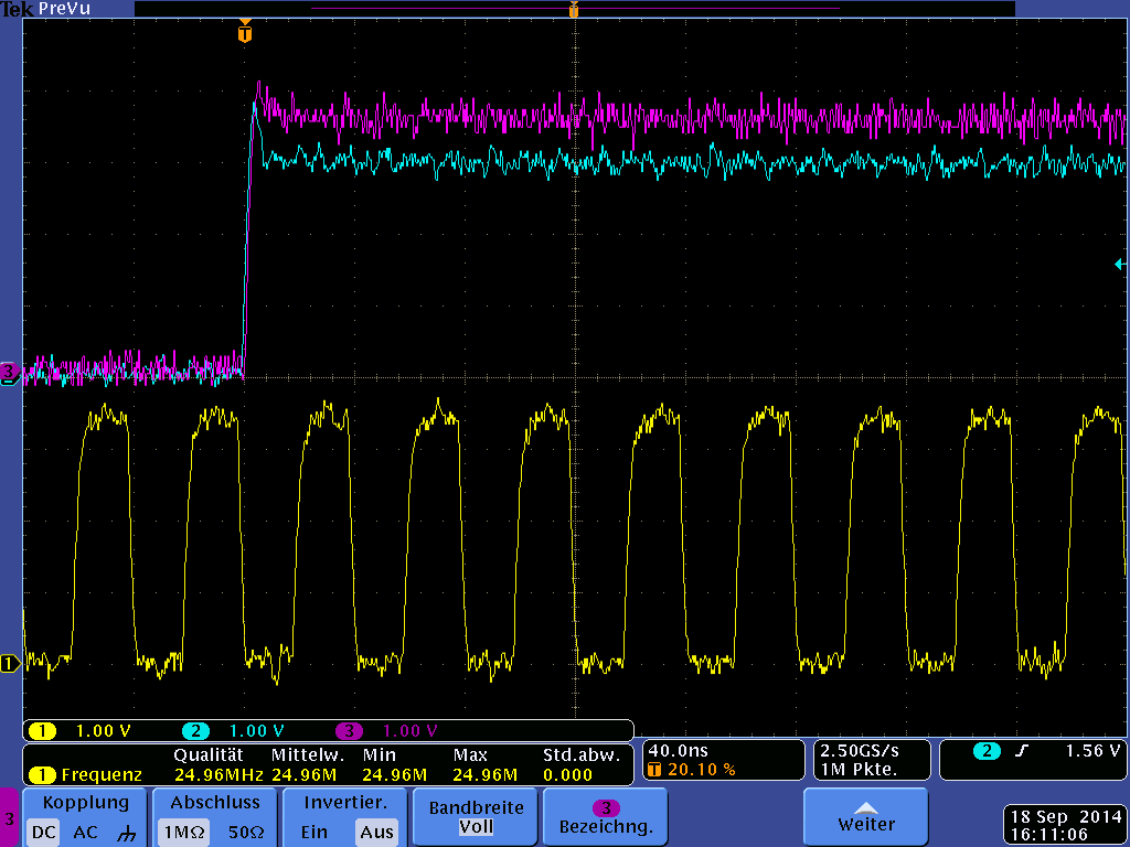
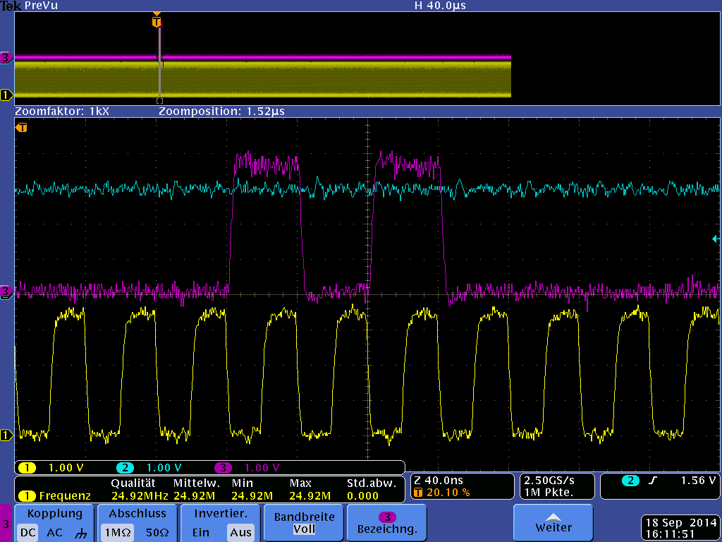
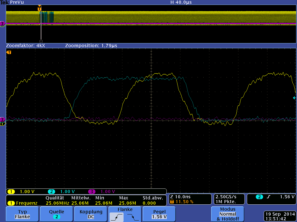
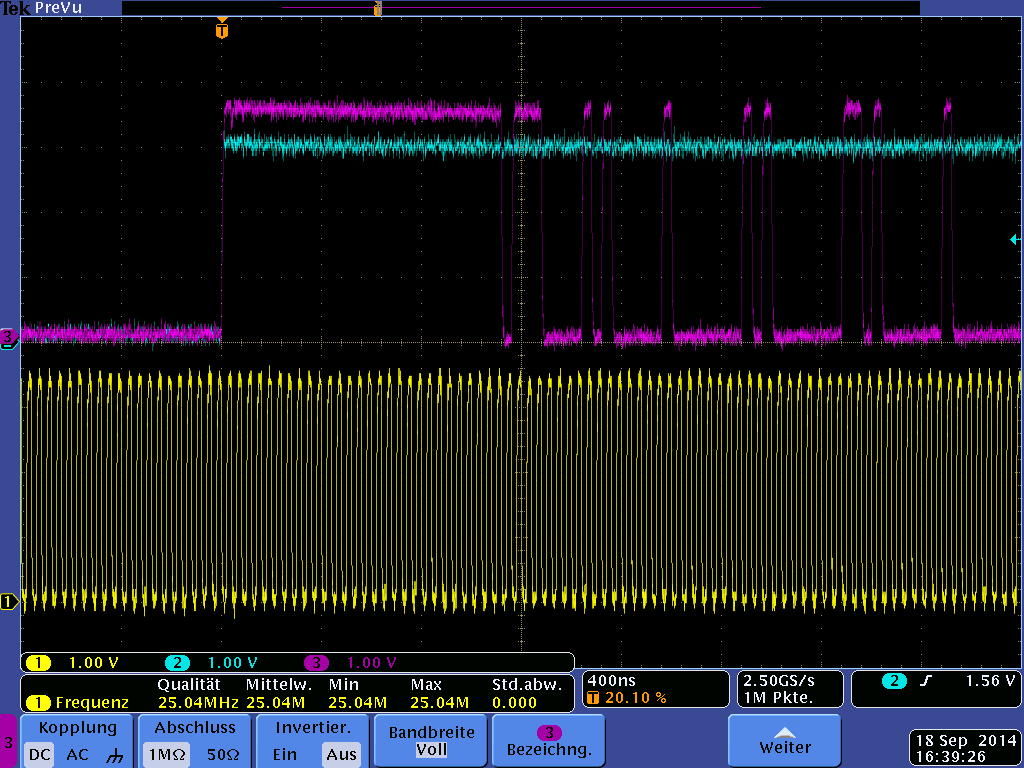
But EtherCAT communication is not possible... When checking the ESC registers (MII Control Reg) within the PRUs, i can see that the ESC lost link counter for Port0 (Reg 0x310) is working properly (tested by connection and removing cable). What seems to be strange is, when connecting the cable to port 1, the link lost counter keeps counting up.

The RX Port0 frame counter (register 0xE00) is counting up when a cable is connected, the one for port 1 isn't detecting any frames. Register 0x300 shows that no invalid frames have been counted for port 0, register 0x301 shows that the rx counter for port 0 is detecting frames. The same registers for port 1 are showing only invalid frames...

For me it seems, that something with the mii interface is messed up, any ideas for that problem or has anyone already sucessfully tested the UPD60621 PHYs with the Sitara?

(The Pinout for MII Interface is exactly the same as on the Phytec carrier board, except that we didn't connect the COL Signals. Changing the Pinmux for the COL Signals on the working carrier board to normal GPIOs had no negativ effect, so i suggest that this is not the problem (could it still be an issue??)).

  • Hi Jens,

    I don't think these PHYs have ever been tested for AM335X EtherCAT communication by TI.

  • Hi Jens,

    it is true that we do not have hardware with these phys. So we can't test. But our goal is to work with any phy that is generally EtherCAT compatible.

    Have you tried the other vendor to help with this? If this is some specifics on their interface they should be able to help.

    Can you clarify if at least Port 0 is working (if your device is only device connected to master)?

    Did you checck the pin-mux? This is an obvious reason for errors especially on port 2 MII...

    What version of IA-SDK are you using?

    Regards,


  • Hi Frank,

    Thank you for the fast reply!

    on the Phytec Developmentboard i use exactly the same software, including the MII pinmux (only the PHY specific code is different) and EtherCAT is working there. On our own hardware, regarding the MII signals we use exactly the same pinout than the Phytec board (except we didn't connect the COL signal). Therefore i assume the pin-mux must be correct.

    Port 0 isn't working using TwinCAT as the master and Sitara as the only slave in the system .

    We already contacted the PHY vendor, because we first assumed that the problem is on the PHY side. They checked for us all the register settings and they seem to be okay. 

    We use SDK 1.1.0.4 with CCS 5.5.

    Any other idea?

    Jens

  • Hi Jens,

    I don't think we need to use COL signal for EtherCAT as it is full duplex anyway.

    Now if the hardware connections are the same and the software works on one version I would assume there is a problem with the MII interface. It seems your phy vendor only checked MDIO regs (which are less critical anyway). But what about the MII signals? Next step would be to check the MII data and clock signals. Do you get any data on a RX when the master is doing something? Do you see the AM335x sending something on TX lines? Obviously you need to compare timing requirements of TI MII interface with the phy too.

    Regards,

  • Hi,


    This may also be related to link polarity differences when enhanced link detection is enabled using rxlink

    http://processors.wiki.ti.com/index.php/AM335x_EtherCAT_firmware_API_guide#bsp_pruss_mdio_init

    • pmdio_params->link0pol: LINK_MII signal polarity of PHY hooked to PRU-ICSS MII0
    • pmdio_params->link1pol: LINK_MII signal polarity of PHY hooked to PRU-ICSS MII1
    • pmdio_params->enhancedlink_enable: Enable enhanced link detection using MII RXLINK and TLK110 enhanced link detection features

    Step1: Look at the value of  PR1_MDIO_ALIVE (@0x4a332408) PR1_MDIO_LINK(@0x4a33240c) registers for following scenarios

    (1) Port0 and Port1 link down

    (2)Port0 and Port1 link up

    Step2: Adjust link0/1 pol accordingly

    Let me know how this goes

  • Hi Frank,

    we already tested the rx and tx signals some time ago (only if they are there) and i rechecked right now that we se the TX clock, tx enable and tx data signals of port 0.

    I couldn't find any documentation about timing requirements of the TI ESC MII , could you provide me this information?


  • Hi Pratheesh,

    i already tried different settings with link0/1 polarity according to the PHY configuration and disabled enhanced link detection for another test without any results.

    Anyway i'll test your suggestions (i didn't check the PR1_MDIO_ALIVE and LINK registers yet) once more to make sure i didn't oversee anything.


    Regards

    Jens

  • Jens,

    I assume you need to download the datasheet again. I think section 7.14.3 with PRU interfaces timing info was only recently added. There are MDIO and MII timings now. Hope that is sufficient.

    Another issue for data errors could be clock accuracy (jitter) or layout issues of course.

    regards,


  • Hi Pratheesh,

    i checked the registers as you suggested:

    PR1_MDIO_ALIVE:

    is always 0xE3, no matter if P0 or P1 is connected

    PR1_MDIO_LINK:

    P0 and P1 down: 0x3

    P0 up, P1 down:  0x2

    P0down, P1 up:   0x1

    link0pol and link1pol have been set to active low and enhanced link detection is enabled

    When i set the link pol to active high i get the following results:

    PR1_MDIO_ALIVE:

    same as before

    PR1_MDIO_LINK:

    P0/P1 down : 0x3

    P0 up P1 down: 0x2

    P0 down, P1 up: 0x3

    Where can i find the information how these registers should behave?

  • Thank you Frank,

    i already tried a better oscillator, because the one we used before didn't match the requirements of the PHY. Unfortunately with no result...

    Regarding the layout we think, that the signals are looking pretty nice :

    Blue: TX_EN

    Lila: TX_D0

    Yellow: TX_CLK

     don't they?

  • Hi Frank,

    we will carefully check the MDIO and MII timings in the Datasheet, we missed this information so far...

  • Hi,

    Jens Kaufmann1 said:

    PR1_MDIO_ALIVE:

    is always 0xE3, no matter if P0 or P1 is connected

    PR1_MDIO_LINK:

    P0 and P1 down: 0x3

    P0 up, P1 down:  0x2

    P0down, P1 up:   0x1

    link0pol and link1pol have been set to active low and enhanced link detection is enabled

    This indicates that both Port0/1 links are active low and shall be configured active low i.e. link0/1pol = 1

    Jens Kaufmann1 said:

    When i set the link pol to active high i get the following results:

    This is not a valid setting.

    Jens Kaufmann1 said:

    Where can i find the information how these registers should behave?

    Refer to AM335x TRM, 14.5.10 MDIO Registers. PRU-ICSS has its own MDIO instance start offset: 0x4a332400

    So it appears that link configuration is fine and from AN_PHY_Selection_GuideV2.3.pdf from Beckhoff, Set P1TXCL=0 for fixed TX_CLK phase shift. From UPD60621 datasheet, this is 1 by default. Did you configure this?

    Also additionally can you tell me the following register values with Port0 and Port1 polarity configured Active Low and PLC/master transmitting to board for 2 cases (1) Port0 only connected (2) Port0 to master  and Port1 to next slave

    0x4a332000, 0x4a332004

    0x4a332010, 0x4a332014

    0x4a332050,  0x4a332054

    0x4a32e080, 0x4a32e084

    0x4a320200, 0x4a320204

  • Hi Pratheesh,

    the configuration for P1TXCLK was set to 1, we changed that over the bootstrap pin to 0, but i still can't detect the EtherCAT slave over TwinCAT. Regarding this, i already had this PHY successfully running on an FPGA- IP Core based ESC with its default settings for P1TXCLK. Anyway we'll keep the new settings P1TXCLK = 0 as suggested in  AN_PHY_Selection_GuideV2.3.pdf, thank you for this hint.

    Here are the values for the registers:

    Case 1, only port 0 connected:

    *0x4a332000 = 0x41,           *0x4a332004 = 0x59

    *0x4a332010 = 0x480401,   *0x4a332014= 0x480700

    *0x4a332050 = 0x0,             *0x4a332054 = 0x0

    *0x4a32e080 = 0xBFFFFF , *0x4a32e084 = 0xFFFF0000

    *0x4a320200 = 0x100,         *0x4a320204=0x44C

    Case 2, port0 connected to master, port 1 connected to other EtherCAT slave

    *0x4a332000 = 0x41,           *0x4a332004 = 0x59

    *0x4a332010 = 0x480701,   *0x4a332014= 0x480401

    *0x4a332050 = 0x1,             *0x4a332054 = 0x5

    *0x4a32e080 = 0xBEFFFF , *0x4a32e084 = 0xFFFFFFFF

    *0x4a320200 = 0x100,         *0x4a320204 = 0x4BC44C

    Hope this information helps!

    Regards,

    Jens


  • Frank,

    we also checked our MII signals today, section 7.14.3 of the datasheet specifies the transmission time of data and clock singals with max. 3ns. Our signals are slower:

    yellow = rxclk, blue = rxd0 and magenta is rxd0 after a multiplexer needed to avoid bootstrap conflicts between Sitara and PHY.

    For having a reference, we measured the same signals of the properly working developmentboard and they are looking pretty similar:

    Could this still be an issue? What do you think about the signals?

    The jitter of our clock is within the specification of the datasheet...

    Regards,

    Jens

  • Jens,

    generally I think I need to skip on that question. I was never involved in debugging an Ethernet interface at that low level so far. From a quick look the timing seems to be good. But I would like to defer that to a real expert. But he will probably ask for schematics first...

    But what port is that? You mentioned earlier that you can recevice on Port 0 but the other Port doesn't get anything. Do you hav wireshark logs too?

    Regards,

  • Frank,

    the signals are measured on port 0...we could see that there is happening something on the rx and tx lines, when the master was trying to connect.

    The wireshark log shows, that there is never coming a response from the sitara side, trying to connect over TwinCAT:

    Providing the schematics shouldn't be a problem, just directly send me a mail.

    Regards

    Jens


  • Frank,

    I just saw that your working in Freising, will you join the TI MCU Design Days next week? I'll be there on both days!

    Have a nice weekend!

    Regards

    Jens

  • Jens Kaufmann1 said:

    Here are the values for the registers:

    Case 1, only port 0 connected:

    *0x4a332000 = 0x41,           *0x4a332004 = 0x59

    *0x4a332010 = 0x480401,   *0x4a332014= 0x480700

    *0x4a332050 = 0x0,             *0x4a332054 = 0x0

    *0x4a32e080 = 0xBFFFFF , *0x4a32e084 = 0xFFFF0000

    *0x4a320200 = 0x100,         *0x4a320204=0x44C

    Case 2, port0 connected to master, port 1 connected to other EtherCAT slave

    *0x4a332000 = 0x41,           *0x4a332004 = 0x59

    *0x4a332010 = 0x480701,   *0x4a332014= 0x480401

    *0x4a332050 = 0x1,             *0x4a332054 = 0x5

    *0x4a32e080 = 0xBEFFFF , *0x4a32e084 = 0xFFFFFFFF

    *0x4a320200 = 0x100,         *0x4a320204 = 0x4BC44C

    Hope this information helps!

    PRU MII interface looks to be programmed correctly in both cases. However I see that from your logs, a number of non-EtherCAT frames are sent by PC to slave. For testing purpose, can you disable all but TwinCAT protocol from NIC properties.

    Does this PHY support odd nibble error handling ? I did not see any reference to same in the datasheet.

    You mentioned there is TX activity  - can you monitor this by sending a NOP frame for example and see TX frame is correctly sent out using scope or sniffer (like netanalyzer).

    Can you also please connect a working board to Port1 and monitor above registers and error counters (both above setup and working board)

    Thanks.

  • PratheeshGangadhar said:
    Does this PHY support odd nibble error handling? I did not see any reference to same in the datasheet.

    I can't find anything about odd nibble error handling in the datasheet either...Is this mandatory?

    One feature of this PHY is, that it can detect the start-of-frame with only the J symbol, without waiting for the K symbol. Does this affect the handling within the PRUs? (I tried both scenarios, seeing no difference, just wondering what's the correct setting)

    PratheeshGangadhar said:
    For testing purpose, can you disable all but TwinCAT protocol from NIC properties.

    I disabled all but TwinCAT protocols on the master side and rechecked the registers:

    With only port 0 connected, I get the same values except for 0x4a32e080. There the value changed to 0xFFFFFFFF

    With port0 connected to the sitara and port1 connected to another slave I got those values:

    *0x4a332000 = 0x41,                *0x4a332004 = 0x59

    *0x4a332010 = 0x480401,        *0x4a332014= 0x480700

    *0x4a332050 = 0x000000,        *0x4a332054 = 0x5

    *0x4a32e080 = 0xFFFFFFFF , *0x4a32e084 = 0x0067035F

    *0x4a320200 = 0x100,              *0x4a320204 = 0x4BD44C

    PratheeshGangadhar said:
    You mentioned there is TX activity  - can you monitor this by sending a NOP frame for example and see TX frame is correctly sent out using scope or sniffer (like netanalyzer).

    This is the only thing I can see with Wireshark:

    Sending a NOP frame from the Sitara side? How can I do that?

    Regards

    Jens


  • PratheeshGangadhar said:
    Can you also please connect a working board to Port1 and monitor above registers and error counters (both above setup and working board)

    Here the registers for the working board:

    only port0 connected:

    *0x4a332408 = 0x7                   *0x4a33240c = 0x2

    *0x4a332000 = 0x41,                *0x4a332004 = 0x59

    *0x4a332010 = 0x480401,        *0x4a332014= 0x480700

    *0x4a332050 = 0x0,                  *0x4a332054 = 0x0

    *0x4a32e080 = 0x00BFFFFF ,  *0x4a32e084 = 0xFFFF0000

    *0x4a320200 = 0x100,               *0x4a320204=0x44C

    port0 connected to sitara and port1 connected to other ecat slave:

    *0x4a332408 = 0x7                   *0x4a33240c = 0x1

    *0x4a332000 = 0x41,                *0x4a332004 = 0x59

    *0x4a332010 = 0x480401,        *0x4a332014= 0x480700

    *0x4a332050 = 0x2,                  *0x4a332054 = 0x2

    *0x4a32e080 = 0x00BEFFFF ,  *0x4a32e084 = 0x0547FFFF

    *0x4a320200 = 0x40100,            *0x4a320204=0x0058C5CC

    To mention is, that the slave on port1 can not be detected by TwinCAT...

    Regards

    Jens

  • Jens Kaufmann1 said:

    I can't find anything about odd nibble error handling in the datasheet either...Is this mandatory?

    This is required for error handling to detect the source of error (odd nibble acts as forwarded error marker). I know that there are ESCs that do not support this feature, but its recommended

    Jens Kaufmann1 said:

    One feature of this PHY is, that it can detect the start-of-frame with only the J symbol, without waiting for the K symbol. Does this affect the handling within the PRUs? (I tried both scenarios, seeing no difference, just wondering what's the correct setting)

    No - this should not, TLK110 also support this feature and enabled by default in Industrial SDK. Called Fast RX_DV detection

    Jens Kaufmann1 said:

    I disabled all but TwinCAT protocols on the master side and rechecked the registers:

    With only port 0 connected, I get the same values except for 0x4a32e080. There the value changed to 0xFFFFFFFF

    With port0 connected to the sitara and port1 connected to another slave I got those values:

    *0x4a332000 = 0x41,                *0x4a332004 = 0x59

    *0x4a332010 = 0x480401,        *0x4a332014= 0x480700

    *0x4a332050 = 0x000000,        *0x4a332054 = 0x5

    *0x4a32e080 = 0xFFFFFFFF , *0x4a32e084 = 0x0067035F

    *0x4a320200 = 0x100,              *0x4a320204 = 0x4BD44C

    This indicates that there is activity on Port1 RX - which is not matching your test setup. Definitely nothing is seen by PRU on Port0. It will help to have 0xE00 value as well...

    Can you please power reset the ICE board before doing the subsequent test. This way status flags will be initialized correctly for a fresh run...

    Jens Kaufmann1 said:

    Sending a NOP frame from the Sitara side? How can I do that?

    I actually meant to send from PC (instead of using TwinCAT) - this is a bit more controlled setup. For eg:- using colasoft packet player or IXIA

  • Jens Kaufmann1 said:

    Here the registers for the working board:

    only port0 connected:

    *0x4a332408 = 0x7                   *0x4a33240c = 0x2

    *0x4a332000 = 0x41,                *0x4a332004 = 0x59

    *0x4a332010 = 0x480401,        *0x4a332014= 0x480700

    *0x4a332050 = 0x0,                  *0x4a332054 = 0x0

    *0x4a32e080 = 0x00BFFFFF ,  *0x4a32e084 = 0xFFFF0000

    *0x4a320200 = 0x100,               *0x4a320204=0x44C

    This really looks good. Is this Phytec board?

    Jens Kaufmann1 said:

    port0 connected to sitara and port1 connected to other ecat slave:

    *0x4a332408 = 0x7                   *0x4a33240c = 0x1

    *0x4a332000 = 0x41,                *0x4a332004 = 0x59

    *0x4a332010 = 0x480401,        *0x4a332014= 0x480700

    *0x4a332050 = 0x2,                  *0x4a332054 = 0x2

    *0x4a32e080 = 0x00BEFFFF ,  *0x4a32e084 = 0x0547FFFF

    *0x4a320200 = 0x40100,            *0x4a320204=0x0058C5CC

    To mention is, that the slave on port1 can not be detected by TwinCAT...

    So network is

    TwinCAT -> Sitara+Micrel -> Sitara+Renesas -> Other ESC

    and above configuration for Sitara+Renesas? What is the link polarity settings (enhanced link detection disabled?)  MDIO/Firmware only detected link on Port0 based on above. So it is not surprising that slave on Port1 is not detected

    Did you check Link LEDs?

  • PratheeshGangadhar said:
    This really looks good. Is this Phytec board?

    Yes these are the registers from the phytec board.

    PratheeshGangadhar said:

    So network is

    TwinCAT -> Sitara+Micrel -> Sitara+Renesas -> Other ESC

    The network was TwinCAT -> Sitara + Micrel (phytecboard) -> Other (working) ESC and the . So there must be an issue with port1 configuration on the phytecboard. (we didn't test port1 before) 

    PratheeshGangadhar said:
    and above configuration for Sitara+Renesas?

    No, the register values are for Sitara+Micrel, port0 connected to TwinCAT and port1 connected to other ESC.

    PratheeshGangadhar said:
    What is the link polarity settings (enhanced link detection disabled?) 

    Link configuration is enhanced link detection enabled and active low polarity for both ports.

    PratheeshGangadhar said:
    Did you check Link LEDs?


    The Link LED on port1 is blinking (2seconds on, 2sec off).

    What could be the reason that the link is getting dropped after 2 seconds?


  • PratheeshGangadhar said:
    Can you please power reset the ICE board before doing the subsequent test. This way status flags will be initialized correctly for a fresh run...

    I'll do this test again next week and make sure to do a power reset before. Then I should also be able to send a NOP frame and measure the signals on the MII interface.

    Have a nice weekend!

    Regards

    Jens

  • Hi Pratheesh,

    we got an option for a redesign and therefore we'll switch to the TLK105 PHYs.  We just spend too much time for this topic and need to move forward. 

    Anyway, thank you for your great support!


    Regards

    Jens

  • Hi,

    Thanks for letting us know. TLK105L might be a good option. Please work with your local TI support...