This thread has been locked.

If you have a related question, please click the "Ask a related question" button in the top right corner. The newly created question will be automatically linked to this question.

TPS65217CRSLR RTC Mode

Other Parts Discussed in Thread: AM3358, BQ32000, TPS65217

Hi,

In beagle Bone Black TPS65217C is used with AM3358 MPU and RTC is also used for this. but in user guide I found that TPS65217C did not support RTC mode only. " 

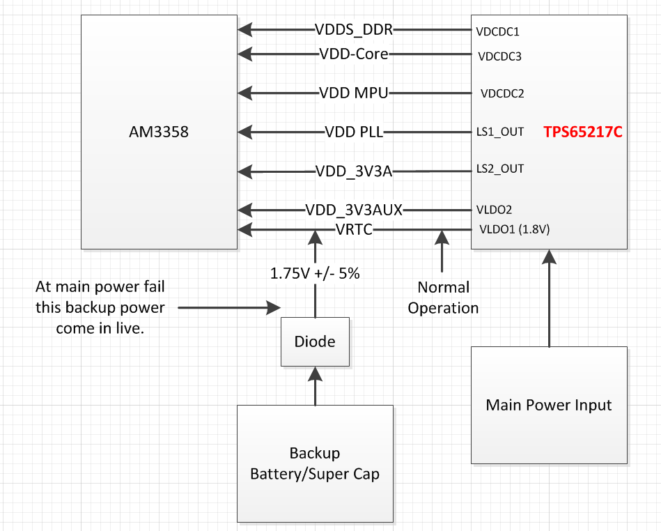
please tell me as in beagle bone black using this same IC RTC signal is also used as VTRC net. can controler will work at loss of power at RTC coin battery or not?

in one forum i fount that use BQ32000 external RTC  is that fine i used an external RTC along with Beagle bone Black reference design.?

TPS65217C is also targeted at the AM335x processor in the ZCZ package, but the DCDC1 output voltage is set to 1.5 V to supply DDR3 memory. This version does not support AM335x RTC-only operation."

in one forum i found that use external RTC

User Guide : Powerring AM3358

http://www.ti.com/lit/ug/slvu551i/slvu551i.pdf

  • an on this following Ti link i found that TPS65217 support RTC only mode. and in User guied which was mentioend in my post said that TPS65217c cannot support RTC only mode. please suggest the right one

    http://processors.wiki.ti.com/images/b/b4/AM335x_PMIC_table.PNG

  • Hi Usman,

    RTC-only mode is a low power mode of the AM335X processor, in which only the internal RTC is powered and active. AM335X internal RTC cannot work from a coin cell, it requires a stable 1.8V +/- 5% power supply. With TPS65217C you can use an external RTC IC for timekeeping. Almost all external RTC's can work from a coin cell, or you can design a dual power supply for it (main/backup through diodes).

  • Thanks Biser,

    its mean I have no need to use any external RTC, if alternate battery power use with diode arrangement as shown in attached block diagram.

  • No, this connection diagram is wrong. VRTC must be 1.8V +/- 5%. See AM335X Datasheet Rev. G section 5.5, requirements for VDDS_RTC.

  • Hi Biser,

    is AM3358 RTC able to works at only availability of VRTC. (i.e. vddr, vdd core, vdd mpu are off)

    (in short i have connect the separate 1.8v to VRTC pin at MPU and power supply TPS65217C switched off)

    and

    I cannot understand why this block diagram (posted in previous post) is wrong, as per section 5.5 of AM335x data sheet VRTC must be 1.8V +/-5%.(1.71 to 1.8volt)| and my back up power provide 1.75 to 1.8 volt as shown is new block diagram attached

    according to TPS65217c data sheet VLDO1 = 1.8V. so if I connect a backup battery with diode arrangement which will give 1.8V volt then why this will connection diagram will not work.

    and this following block diagram is ok?


    please clear me is this arrangement are wrong what will be the right way to connect this.

  • 1.75V +/- 5% makes a voltage range from 1.6625V to  1.8375V. The recommended range is from 1.710V to 1.890V.

  • I would also like to underline that VRTC needs to be a stabilized power supply. A coin cell/supercap cannot provide this.

  • oh, sorry. got this. i mean to say that 1.75VOlt are min voltage provided by backup. by mistake i have mentioned +/-5% with this
  • last 1 thing,
    if Only VRTC is on/available (1.8V) at AM3358 and all other powers are off (i.e. VDD MPU, VDD Core, VDD DDR, VDD 3V3) then is AM3358 is capable to run its internal RTC.?
  • I checked the TPS65217 User Guide. The reason it states that TPS65217C/D cannot be used for RTC-only mode is that in the connection diagram VDDS is also supplied from LDO1. You can supply VDDS however, from LDO3 and leave LDO1 only for VDDS_RTC. In this case however you will need to have a Li+ battery attached to the PMIC if you intend to remove external power completely..

  • Usman Afzal said:
    last 1 thing,
    if Only VRTC is on/available (1.8V) at AM3358 and all other powers are off (i.e. VDD MPU, VDD Core, VDD DDR, VDD 3V3) then is AM3358 is capable to run its internal RTC.?

    This is RTC_Only mode exactly.

  • Thanks Biser for your kind support.

    I think now i am got the solution  and this following image circuit is fine as, now i am connection VDDS and VIO at LDO3 along With VDD1v8 net and  VLDO1 has only VTRC signal net. and Li batt.

    previously VIO and VDDS are connected at VLDO1 along with VRTC.

    in above sch now i am going to DNI R8 and R9 will install. and R7 will connect at pin 40 instead of pin 3 of tps65217c

  • Attaching a battery cell directly to the VRTC power rail is absolutely unacceptable. When I mentioned battery, I meant the BAT pins of the PMIC. Please find some time and read the TPS65217C datasheet.

  • Hi Biser,

    Good discussion here on RTC, but I am still not clear on how to run RTC-only mode on AM335x with TPS65217C. Is this not possible at all, as stated in the User Guide, or there is a way using another technique (dedicated power supply to RTC_VCC?).

    Thanks for the clarification.

    ~Leonard 


  • Hi Leonard,

    Which user guide are you referring to? This link shows that RTC-only mode is supported by TPS65217: http://processors.wiki.ti.com/index.php/Device:AM335x:Device_Evaluation#Power

  • This is from the TPS65217C User Guide:  http://www.ti.com/lit/ug/slvu551i/slvu551i.pdf

     “TPS65217C is also targeted at the AM335x processor in the ZCZ package, but the DCDC1 output voltage is set to 1.5 V to supply DDR3 memory. This version does not support AM335x RTC-only operation.”

    His reply is: 

    Our product will run off Li-Ion cell battery connected to the TPS65217C. This must be a valid battery option.  I was only confused by the statement in the user guide that TPS65217C doesn’t support RTC-only mode.  I think the thread you suggested provides an answer:

     “I checked the TPS65217 User Guide. The reason it states that TPS65217C/D cannot be used for RTC-only mode is that in the connection diagram VDDS is also supplied from LDO1. You can supply VDDS however, from LDO3 and leave LDO1 only for VDDS_RTC. In this case however you will need to have a Li+ battery attached to the PMIC if you intend to remove external power completely..

    So basically it has nothing to do with the PMIC itself – it’s the way the PMIC is connected to the rest of the system. In our design VLDO1 is connects to the VDDS_RTC only so theoretically RTC-only mode should work fine.

    So it seems he is not going to configure in the same manner as the EVM, with the supplies connected together.

    ~Leonard 


  • I agree with his comments - the way he suggests connecting VDDS should work for RTC-only mode.

  • I am also looking into implementing this modification to the connection of VDD_RTC.    One thing that was not addressed in the response is whether it is appropriate to connect VIO to VDD_RTC or 1.8V.   The difference would be whether the PGOOD and LDO_PGOOD signals can be driven to the processor when in RTC only mode.  It seem like they should not be driven when the only power is VDD_RTC, so therefore counter to the manual VIO should get connected to 1.8V on LDO3, is that correct?

    Also, I've been chasing a comment on the BBB board discussing the need to connect VDDS to VDD_RTC because of a requirement from TI - the only thing I can find relating to this is the power down sequence, 335x datasheet, rev H states:  "The VDDS power supply must ramp down after all 3.3-V VDDSHVx [1-6] power supplies."   I can't see how connecting VDDS to LDO3 could create this problem, any advice here?

  • I've looked into the VIO thing further and see that all of the inputs that go to the am335x are powered by VDD_RTC, so there is no issue - it is pretty clear that VIO should be connected to VDD_RTC.

    The outstanding question is my second:

    Also, I've been chasing a comment on the BBB board discussing the need to connect VDDS to VDD_RTC because of a requirement from TI - the only thing I can find relating to this is the power down sequence, 335x datasheet, rev H states: "The VDDS power supply must ramp down after all 3.3-V VDDSHVx [1-6] power supplies." I can't see how connecting VDDS to LDO3 could create this problem, any advice here?
  • VDDS connected to LDO3 should not create any problems. VDDS to VDD_RTC is not a proper connection and is not recommended.