

Hello,
There are many "standard" resolutions defined in the IPNC_RDK. There is also a macro for FVID2_STD_CUSTOM.
How is this custom resolution defined and used throughout the usecases and drivers?
Thanks,
Mechi

This thread has been locked.
If you have a related question, please click the "Ask a related question" button in the top right corner. The newly created question will be automatically linked to this question.
Hello,
There are many "standard" resolutions defined in the IPNC_RDK. There is also a macro for FVID2_STD_CUSTOM.
How is this custom resolution defined and used throughout the usecases and drivers?
Thanks,
Mechi

Hi Brijesh,
I made the correct changes in issdrv_mt9j003Api.c and issdrv_mt9j003_config.h. My new resolution "masquerades" as the "default" 1080p. Everywhere that 1920x1080 is in the code (for width and height) I substituted 1200x1200 (binning from 2400x2400) - in the links, usecase, and iss driver.
But this is not a very nice solution. There were many, many substitutions. I was asking if there's somewhere that I can define my custom resolution including WIDTH and HEIGHT and it would be recognized throughout the IPNC RDK?
Thanks,
Mechi
I haven't figured out how to attach files.
The changes are in the following files:
ipnc_rdk/ipnc_mcfw/demos/mcfw_api_demos/multich_usecase/ti_mcfw_ipcbits.c
ipnc_rdk/ipnc_mcfw/demos/mcfw_api_demos/multich_usecase/ti_mcfw_ipnc_main.c
ipnc_rdk/ipnc_mcfw/mcfw/src_bios6/links_m3vpss/camera/cameraLink_drv.c
ipnc_rdk/ipnc_mcfw/mcfw/src_bios6/links_m3vpss/capture/captureLink_drv.c
ipnc_rdk/ipnc_mcfw/mcfw/src_bios6/links_m3vpss/system/system_m3vpss.c
ipnc_rdk/ipnc_mcfw/mcfw/src_linux/links/ipcBitsOut/ipcBitsOutLink_tsk.c
ipnc_rdk/ipnc_mcfw/mcfw/src_linux/mcfw_api/usecases/multich_tristream_fullfeature.c
ipnc_rdk/ipnc_mcfw/mcfw/src_linux/mcfw_api/ti_vdis.c
ti_tools/iss_03_80_00_00/packages/ti/psp/devices/mt9j003/src/issdrv_mt9j003Api.c
ti_tools/iss_03_80_00_00/packages/ti/psp/devices/mt9j003/issdrv_mt9j003_config.h
ti_tools/iss_03_80_00_00/packages/ti/psp/iss/drivers/capture/src/issdrv_captureApi.c
ti_tools/iss_03_80_00_00/packages/ti/psp/iss/drivers/capture/src/issdrv_capturePriv.h
The actual sensor settings are in issdrv_mt9j003_config.h.
Registers are set in order to get an ROI of 2400x2400 centered in the middle of the sensor for our fish-eye lens and then binning to yield 1200x1200 is as follows:
// default - was 1080p30fps - changed to 1200x1200 - 20fps
UInt32 SensorConfigScript[69][3] = {
{0x030A, 2, 0x00},
{100, 0, 100},
{0x030A, 2, 0x01},
{100, 0, 100},
{0x0100, 2, 0x00},
{100, 0, 100},
{0x0300, 2, 0x3},
{0x0302, 2, 0x1},
{0x0304, 2, 0x1},
{0x0306, 2, 32}, //48}, // pll multiplier
{0x0308, 2, 0x0C},
{0x030A, 2, 0x01}, // op_sys_clk_divider
{100, 0, 100},
{0x0104, 2, 0x01},
{0x3064, 2, 0x805},
{0x3016, 2, 0x121},
{0x0344, 2, 840}, //0x012},
{0x0348, 2, 3239}, //0xF13},
{0x0346, 2, 50}, //0x8},
{0x034A, 2, 2449}, //0x879},
{0x3040, 2, 0x28C3}, // low power + summing
{0x0400, 2, 0x0002},
{0x0404, 2, 0x0010},
{0x034C, 2, 1200}, //0x782},
{0x034E, 2, 1200}, //0x43A},
{0x0342, 2, 2200}, //0x0881},
{0x0340, 2, 1832}, //0x04c9},
{0x0202, 2, 1575}, //1212}, // coarse integration
{0x3014, 2, 0x0603},
{0x3010, 2, 0x009C},
{0x3018, 2, 0x0000},
{0x30D4, 2, 0xB080},
{0x306E, 2, 0x90B0},
{0x3E00, 2, 0x0010},
{0x3070, 2, 0x0000}, // 2}, //test pattern
{0x31C6, 2, 0x8400},
{0x3E00, 2, 0x0010},
{0x3EDC, 2, 0xD8E4},
{0x3178, 2, 0x70}, //0x0070},
{0x3170, 2, 0x00E5},
{0x3ECC, 2, 0x0FE4},
{0x316C, 2, 0x0429},
{0x3174, 2, 0x8000},
{0x3E40, 2, 0xDC05},
{0x3E42, 2, 0x6E22},
{0x3E44, 2, 0xDC22},
{0x3E46, 2, 0xFF00},
{0x3ED4, 2, 0xF998},
{0x3ED6, 2, 0x9789},
{0x3EDE, 2, 0xE438},
{0x3EE0, 2, 0xA43F},
{0x3EE2, 2, 0xA4BF},
{0x3EEC, 2, 0x1C21},
{0x3056, 2, 0x1040},
{0x3058, 2, 0x1040},
{0x305A, 2, 0x1040},
{0x305C, 2, 0x1040},
{0x301A, 2, 0x0010},
{0x3064, 2, 0x0805},
{0x301E, 2, 0x00A8},
{0x0400, 2, 0x0000},
{0x306E, 2, 0x9080},
{0x31AE, 2, 0x0304},
{0x301A, 2, 0x001C},
{0x0104, 2, 0x00},
{0x0120, 2, 0x00},
{0x305e, 2, 0x1040},
{0x0202, 2, 1175}, //1175}, // coarse integration - why twice??
{10, 0, 0}
};
I would be interested if there's a way to specify this resolution, and register settings would yield it.
More important, though, is the ability to specify a custom resolution and it should be recognized throughout the IPNC_RDK. The changes that I had to make in the files above were basically just changing 1920x1080 to 1200x1200.
Thanks,
Mechi
Hi,
Sorry,I oversaw your reply you have already listed the modified files.
Can you pl. send us the files you modified?
You can click on the 'Use rich formatting' button after clicking on Reply button and then insert the files by clicking on the 'Insert/Edit Media' button.
regards,
Anand
I tried to attach a zip with all of the changed files.
As I've mentioned, I had to disable the SALDRE since it didn't work well with this resolution.
Another thing, even though I defined everywhere that I'm working with 1200x1200, the AEC seems to "think" that there's much black and therefore, when filming outside, the whole frame is totally saturated.
I hope you'll be able to help with this,
Thanks,
Mechi
Hi,
It looks like you have replaced all the instances of 1920 with 1200 in the mcfw code, but the only valid changes are in the following files:
All the other instances are used either for HDMI display or limit values.
Regarding the AE for 1200x1200 case, can you pl. use the following values in the 'Iss_Mt9j003UpdateExpGain()' fn in ..\ti_tools\iss_03_80_00_00\packages\ti\psp\devices\mt9j003\src\issdrv_mt9j003Api.c file to calculate the sensor integration time?
For 1200x1200 resolution, pixel clock = (10 * 32)/3 = 106 MHz and line_length_pck = 2200
PixelClock = 106; // MT9J_003_PIXEL_CLOCK;
LineLength = 2200;
regards,
Anand
Hi,
The pixel clock is computed as follows:
Pixel clock = (Master clock * pll_multiplier)/(pre_pll_clk_div * vt_pix_clk_div * vt_sys_clk_div);
And the line_lenth_pck (0x342) is the no of pixel clocks per line.
So the row tme = line_lenth_pck/Pixel clock.
The exposure time which is output by the AE algorithm is in terms of usec which you need to map to the no of lines (exposureTime/row time) of the sensor.
The max width is used for allocating the bit stream buffers in ipc bits out link so if you want to save on the memory you can go and change the value to 1200 otherwise there is no other side effect.
Can you pl. disable SALDRE and observe the video in out door light?
Can you send me the video clip where it becomes bright pink?
regards,
Anand
Hello Anand,
I really appreciate your explanations.
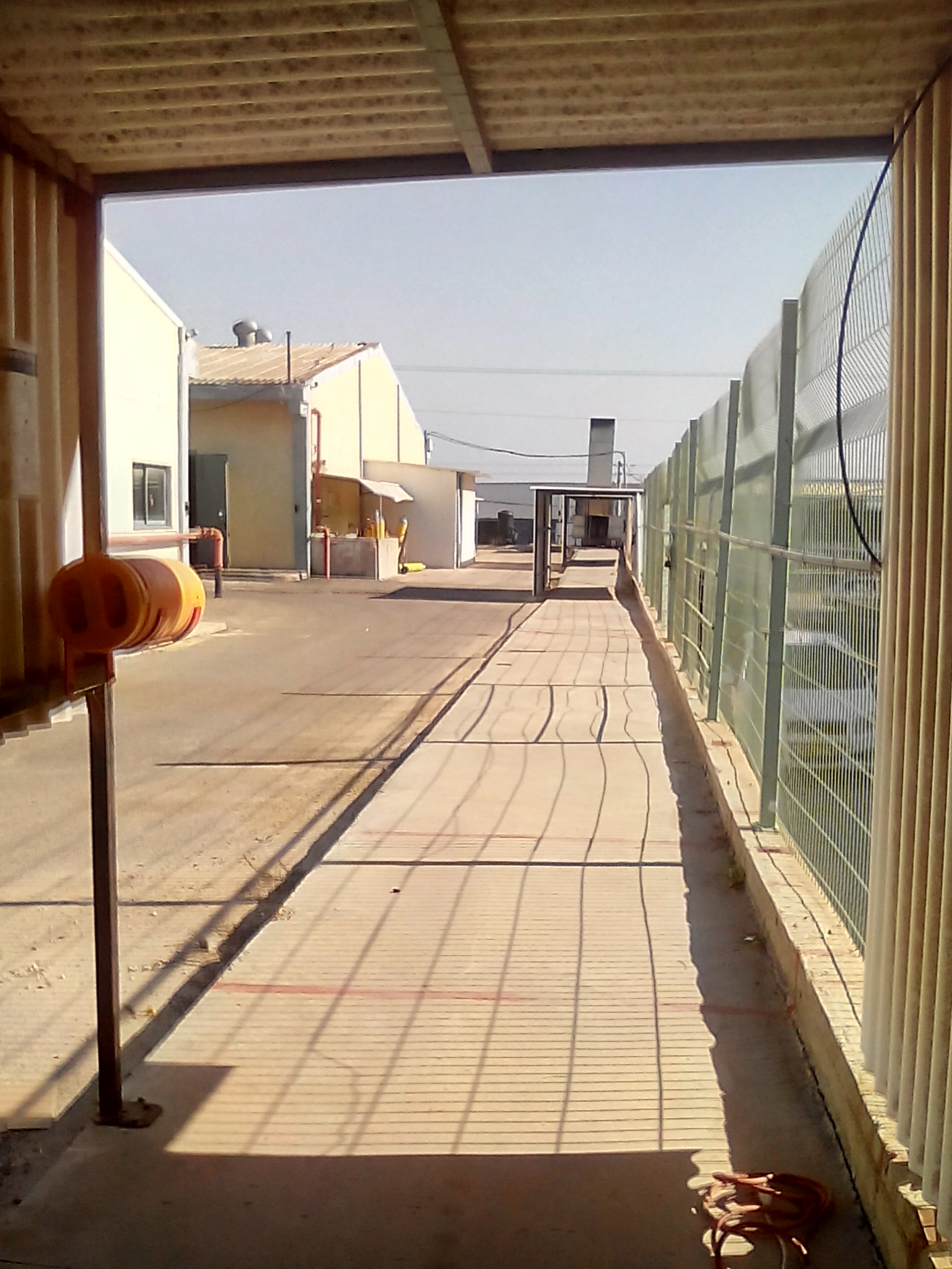
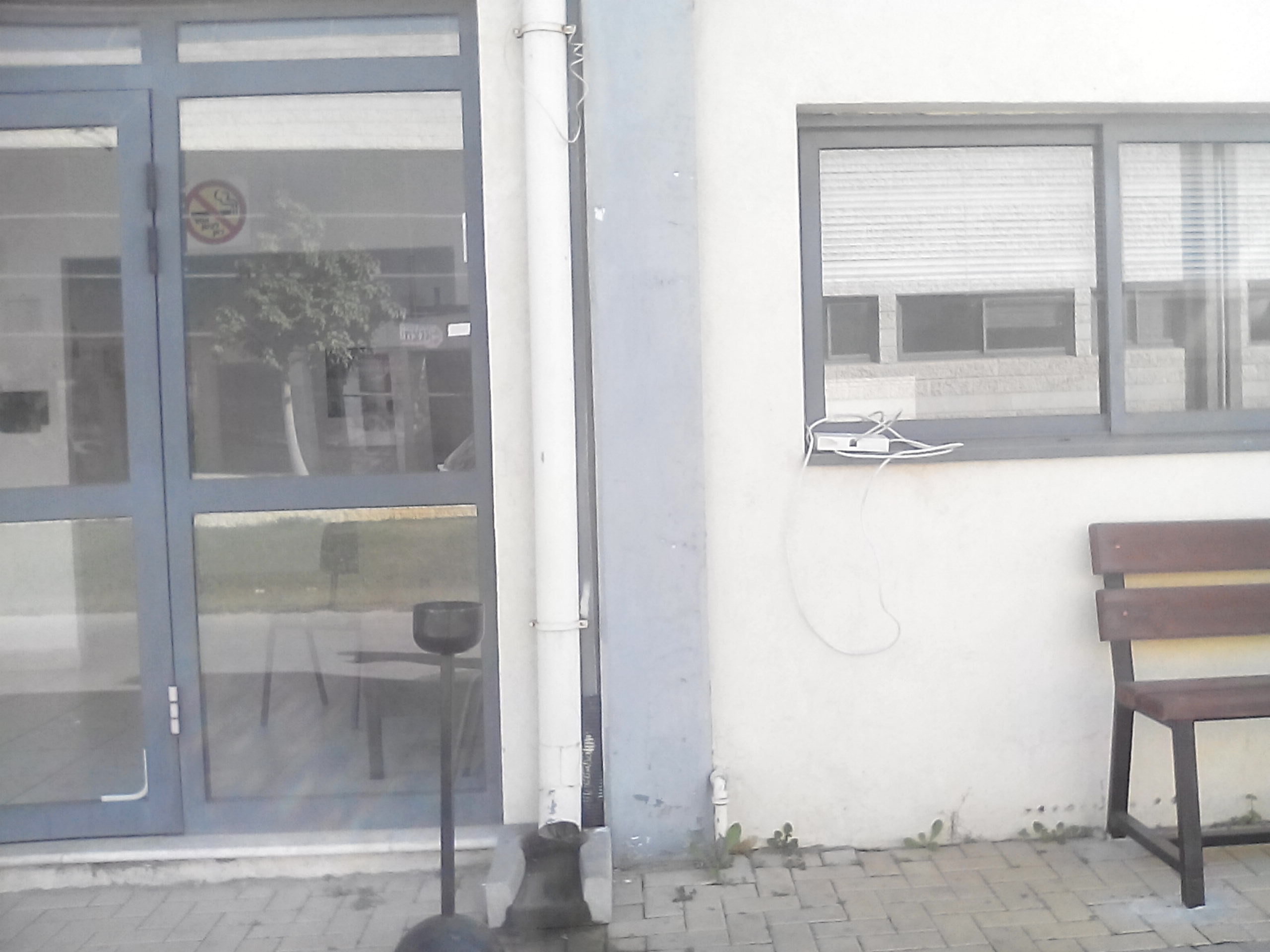
I went back to the original tri-stream full-feature usecase, 1920x1080. I did a NAND-scrub and burned the UBI_FileSystem, uImage, and uBoot files. Without SALDRE and also with SALDRE, here is the a frame captured from the camera. Attached is also a frame from my smartPhone - so you can see the way colors should be. TI's 2A engine - AutoExposure was set with average brightness at 60. AutoWhiteBalance gives worse colors, so it was disabled.
Our camera will have to work in bright sunlight, dusk, rain, etc. We must be able to work with all types of lighting conditions.

Here's the "real" colors:
Hi Anand'
I think I may have figured out why this "pink" problem occurs.
I wasn't using the original uImage when I took the previous pictures. I replaced with the original uImage, and the pictures were closer to the real color.
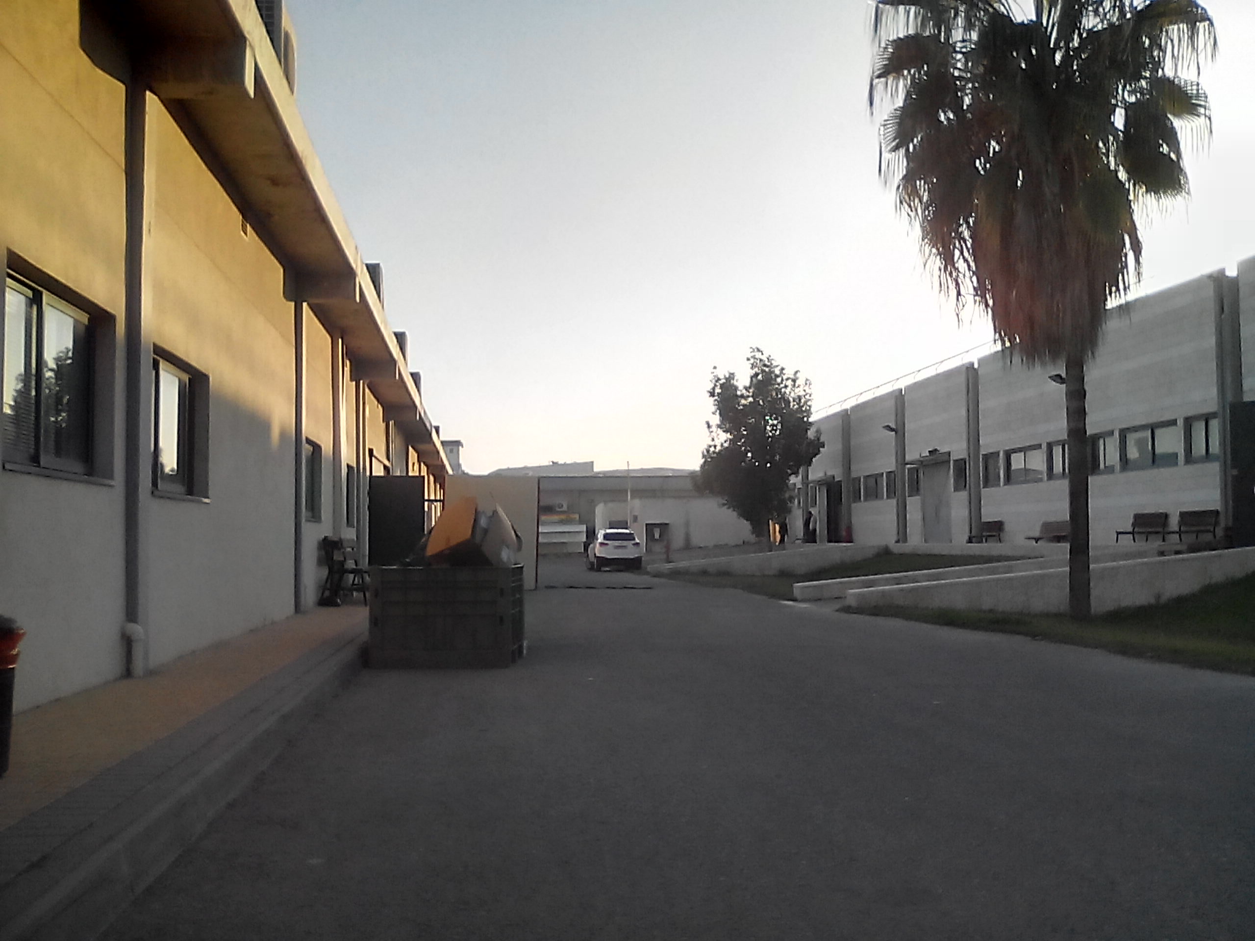
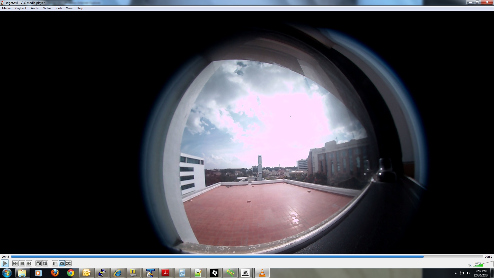
Then I put on the fish-eye lens that I will be using for the final camera, and without changing to the 1200x1200 driver, I got pictures with much pink. I think that since the camera "sees" alot of black on the sides of the actual picture, it tries to compensate and therefore the gains are raised - causing the pink. It would be nice to be able to define an ROI for the AEWB... But when I use my driver of 1200x1200, still I get the pink - which means that the AEWB is still taking into account all of the black surrounding area.
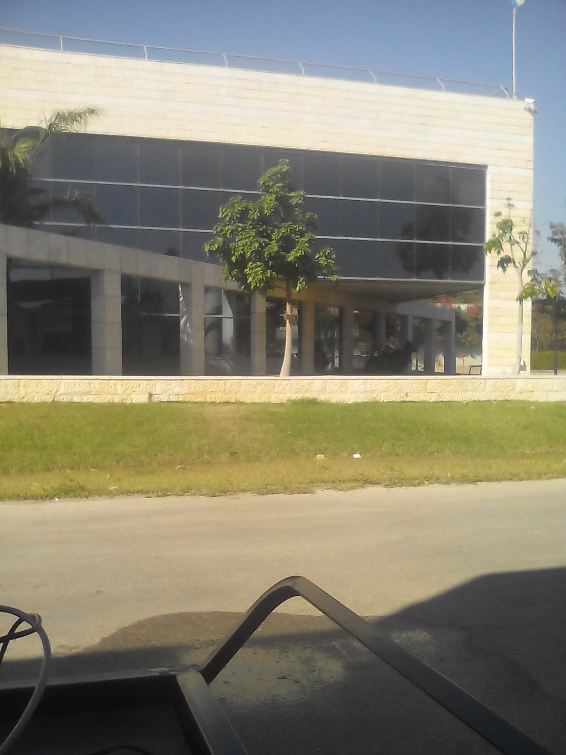
Below is from my smartPhone - the "real" colors (though the sky should be a bit bluer):
Here's the picture using the fish-eye lens with default usecase 1920x1080. I tried with/without SALDRE and lowering the brightness, which didn't help - since it's trying to compensate for the black areas.
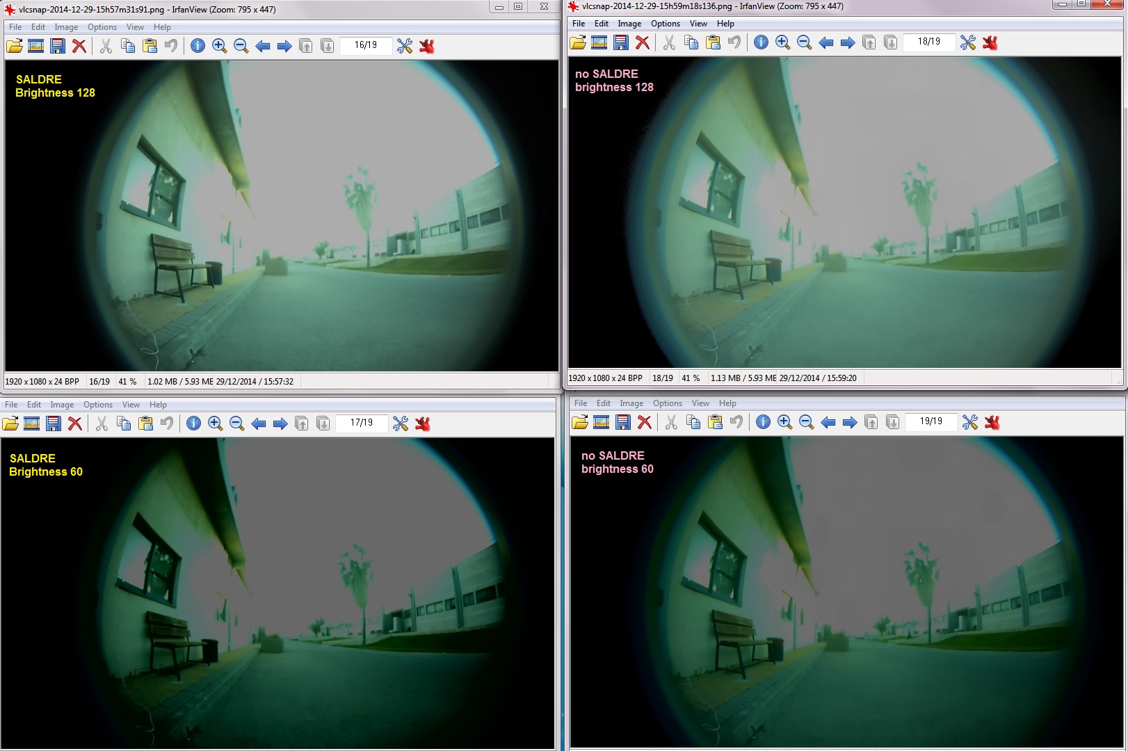
Using the new driver that I defined 1200x1200 (and sent you the files) with the following change:
0x342 = 1300
and PixelClock = 106; // MT9J_003_PIXEL_CLOCK;
LineLength = 2200;
I thought that since the driver is 1200x1200, the black areas are much smaller and the picture would be better.
Video clip has 2 scenes which are shown in attached pictures.
Hi,
First can you make sure you get the 1080p use case working w.r.t AEWB?
I have tested the 1080p use case with Fish eye lens in the outdoor condition and AEWB is working fine.
Pl. find the snapshot attached.
I remember you mentioned the following files:
\ti_tools\iss_03_80_00_00\packages\ti\psp\iss\drivers\alg\2A\src\issdrv_algTIaewb.c
\ti_tools\iss_03_80_00_00\packages\ti\psp\iss\alg\aewb\ti2a\fd\inc\alg_ti_flicker_detect.h
\ti_tools\iss_03_80_00_00\packages\ti\psp\iss\alg\aewb\ti2a\ae\src\ae_ti.c
Did you make any changes in these files.
Also for 1080p you have to use PixelClock = 160; and LineLength = 2177;
You may run the pre built binaries from the IPNC RDK ver 3.8 release.
regards,
Anand
Hi,
I have tried 1200x1200 resolution on my side.
Pl. find my patch attached.
Refer to the 'Files_modified.txt' file for the list of files modified to support 1200x1200 resolution.
regards,
Anand
I have a few logs in which the AEWB data is printed. I will upload them.
When I covered up the sky in the picture, the bottom half of the picture is mostly OK.

The 3 attached logs are as follows:
2. changed brightness from 128 to 68
3. covered half of frame - as seen in picture above
Hello Anand,
I did exactly what you suggested (burning the original, default usecase into the NAND) and the results are in the post from Dec 29, 2014 11:57 AM. I did a NAND scrub and put in the original filesystem. I did it again yesterday with the same results.
The SALDRE gives me black/white screens overlaying the original frames - how is this to be stopped? It happened in the default usecase on the NAND.
I'm continuing in the thread about AEWB/SALDRE for custom resolutions - since the title question "How to define a new resolution" was basically answered in Anand's code that he sent.
I'm having an interesting problem of "motion lines" in the RAW frame.
Please see post http://e2e.ti.com/support/dsp/davinci_digital_media_processors/f/716/t/409837
Can this be related to the custom resolution of 1200x1200?
Are these lines coming from the SALDRE or some sort of DMVA code?
Thanks,
Mechi

![Fullscreen changedBrightness68.txt Download [m3vpss ] DSP AE: [m3vpss ] nextExposure: 10000, curExposure:10000 [m3vpss ] nextGain: 1000, curGain:1000 [m3vpss ] nextIGain: 200, curIGain:200 [m3vpss ] DSP AE: [m3vpss ] nextExposure: 10000, curExposure:10000 [m3vpss ] nextGain: 1000, curGain:1000 [m3vpss ] nextIGain: 200, curIGain:200 [m3vpss ] DSP AE: [m3vpss ] nextExposure: 10000, curExposure:10000 [m3vpss ] nextGain: 1000, curGain:1000 [m3vpss ] nextIGain: 200, curIGain:200 [m3vpss ] DSP AE: [m3vpss ] nextExposure: 10000, curExposure:10000 [m3vpss ] nextGain: 1000, curGain:1000 [m3vpss ] nextIGain: 200, curIGain:200 [m3vpss ] #### VD int [m3vpss ] DSP AE: [m3vpss ] nextExposure: 10000, curExposure:10000 [m3vpss ] nextGain: 1000, curGain:1000 [m3vpss ] nextIGain: 200, curIGain:200 [m3vpss ] pixCtWin=36,WinVNum=32,WinHNum=16, [m3vpss ] ******* H3A DUMP Start ******** [m3vpss ] =====R Data===== [m3vpss ] [ 0] 18, 139, 313, 1180, 1634, 1718, 1719, 1719, 1719, 1718, 1682, 1534, 1305, 1014, 495, 145, [m3vpss ] [ 1] 32, 263, 613, 1602, 1719, 1719, 1719, 1719, 1719, 1719, 1719, 1690, 1505, 1235, 847, 273, [m3vpss ] [ 2] 115, 294, 1135, 1718, 1719, 1719, 1719, 1719, 1719, 1719, 1719, 1719, 1666, 1433, 1108, 542, [m3vpss ] [ 3] 248, 292, 1606, 1719, 1719, 1719, 1719, 1719, 1719, 1719, 1719, 1719, 1718, 1613, 1317, 875, [m3vpss ] [ 4] 317, 578, 1719, 1719, 1719, 1719, 1719, 1719, 1719, 1719, 1719, 1719, 1719, 1709, 1508, 1148, [m3vpss ] [ 5] 318, 959, 1719, 1719, 1719, 1719, 1719, 1719, 1719, 1719, 1719, 1719, 1719, 1719, 1675, 1372, [m3vpss ] [ 6] 300, 1284, 1719, 1719, 1719, 1719, 1719, 1719, 1719, 1719, 1719, 1719, 1719, 1719, 1717, 1571, [m3vpss ] [ 7] 360, 1565, 1719, 1719, 1719, 1719, 1719, 1719, 1719, 1719, 1719, 1719, 1719, 1719, 1719, 1692, [m3vpss ] [ 8] 513, 1719, 1719, 1719, 1719, 1719, 1719, 1719, 1719, 1719, 1719, 1719, 1719, 1719, 1719, 1719, [m3vpss ] [ 9] 745, 1719, 1719, 1719, 1719, 1719, 1719, 1719, 1719, 1719, 1719, 1719, 1719, 1719, 1719, 1719, [m3vpss ] [ 10] 924, 1719, 1719, 1719, 1719, 1719, 1719, 1719, 1719, 1719, 1719, 1719, 1719, 1719, 1719, 1719, [m3vpss ] [ 11] 1071, 1719, 1719, 1719, 1719, 1719, 1719, 1719, 1719, 1719, 1719, 1719, 1719, 1719, 1719, 1719, [m3vpss ] [ 12] 1211, 1719, 1719, 1719, 1669, 1719, 1719, 1719, 1719, 1719, 1719, 1719, 1719, 1719, 1719, 1719, [m3vpss ] [ 13] 1027, 1719, 1719, 1666, 1357, 1634, 1719, 1719, 1719, 1719, 1719, 1719, 1719, 1719, 1719, 1570, [m3vpss ] [ 14] 919, 1719, 1719, 1571, 1426, 1653, 1719, 1719, 1719, 1719, 1719, 1719, 1719, 1660, 1418, 1130, [m3vpss ] [ 15] 904, 1719, 1719, 1490, 834, 1462, 1719, 1719, 1719, 1719, 1719, 1718, 1649, 1173, 1162, 772, [m3vpss ] [ 16] 968, 1719, 1719, 1425, 715, 1502, 1719, 1719, 1719, 1719, 1719, 1680, 1523, 886, 402, 380, [m3vpss ] [ 17] 1019, 1719, 1719, 1573, 808, 1594, 1719, 1719, 1719, 1510, 1688, 1643, 1511, 859, 257, 324, [m3vpss ] [ 18] 1127, 1719, 1719, 1719, 914, 1719, 1719, 1719, 1719, 1426, 1591, 1508, 1439, 872, 446, 494, [m3vpss ] [ 19] 1137, 1700, 1719, 1719, 1054, 1694, 1666, 1678, 1710, 1369, 1477, 1148, 824, 516, 461, 310, [m3vpss ] [ 20] 1106, 1492, 1418, 1666, 1386, 1569, 1556, 1443, 1355, 929, 805, 577, 775, 651, 333, 302, [m3vpss ] [ 21] 603, 744, 812, 1182, 1089, 980, 703, 1087, 1244, 918, 1137, 1297, 1116, 809, 341, 262, [m3vpss ] [ 22] 399, 617, 762, 1067, 1077, 1040, 778, 1306, 1429, 1183, 1240, 1271, 851, 767, 573, 491, [m3vpss ] [ 23] 236, 531, 555, 733, 812, 690, 681, 1111, 1170, 1023, 921, 798, 611, 441, 301, 232, [m3vpss ] [ 24] 270, 510, 601, 596, 525, 417, 435, 417, 444, 398, 356, 323, 276, 240, 241, 252, [m3vpss ] [ 25] 285, 532, 556, 570, 607, 593, 544, 460, 454, 424, 399, 357, 317, 353, 409, 397, [m3vpss ] [ 26] 233, 468, 555, 552, 543, 575, 608, 656, 676, 650, 601, 575, 546, 478, 412, 355, [m3vpss ] [ 27] 191, 428, 516, 546, 544, 537, 547, 556, 564, 544, 517, 484, 446, 398, 356, 304, [m3vpss ] [ 28] 157, 376, 460, 518, 541, 536, 530, 517, 515, 496, 470, 433, 401, 367, 334, 301, [m3vpss ] [ 29] 143, 315, 407, 463, 502, 526, 523, 526, 509, 484, 446, 409, 383, 366, 327, 298, [m3vpss ] [ 30] 136, 288, 367, 425, 460, 481, 503, 506, 497, 479, 443, 411, 383, 360, 326, 298, [m3vpss ] [ 31] 133, 234, 343, 401, 422, 443, 469, 490, 472, 459, 429, 403, 382, 355, 312, 265, [m3vpss ] =====G Data===== [m3vpss ] [ 0] 24, 243, 476, 1623, 1719, 1719, 1719, 1719, 1719, 1719, 1719, 1719, 1719, 1618, 866, 232, [m3vpss ] [ 1] 54, 415, 864, 1719, 1719, 1719, 1719, 1719, 1719, 1719, 1719, 1719, 1719, 1717, 1424, 467, [m3vpss ] [ 2] 204, 428, 1298, 1719, 1719, 1719, 1719, 1719, 1719, 1719, 1719, 1719, 1719, 1719, 1680, 941, [m3vpss ] [ 3] 404, 421, 1657, 1719, 1719, 1719, 1719, 1719, 1719, 1719, 1719, 1719, 1719, 1719, 1719, 1456, [m3vpss ] [ 4] 491, 724, 1719, 1719, 1719, 1719, 1719, 1719, 1719, 1719, 1719, 1719, 1719, 1719, 1719, 1690, [m3vpss ] [ 5] 458, 1071, 1719, 1719, 1719, 1719, 1719, 1719, 1719, 1719, 1719, 1719, 1719, 1719, 1719, 1719, [m3vpss ] [ 6] 426, 1371, 1719, 1719, 1719, 1719, 1719, 1719, 1719, 1719, 1719, 1719, 1719, 1719, 1719, 1719, [m3vpss ] [ 7] 493, 1616, 1719, 1719, 1719, 1719, 1719, 1719, 1719, 1719, 1719, 1719, 1719, 1719, 1719, 1719, [m3vpss ] [ 8] 658, 1719, 1719, 1719, 1719, 1719, 1719, 1719, 1719, 1719, 1719, 1719, 1719, 1719, 1719, 1719, [m3vpss ] [ 9] 867, 1719, 1719, 1719, 1719, 1719, 1719, 1719, 1719, 1719, 1719, 1719, 1719, 1719, 1719, 1719, [m3vpss ] [ 10] 1016, 1719, 1719, 1719, 1719, 1719, 1719, 1719, 1719, 1719, 1719, 1719, 1719, 1719, 1719, 1719, [m3vpss ] [ 11] 1162, 1719, 1719, 1719, 1719, 1719, 1719, 1719, 1719, 1719, 1719, 1719, 1719, 1719, 1719, 1719, [m3vpss ] [ 12] 1303, 1719, 1719, 1719, 1700, 1719, 1719, 1719, 1719, 1719, 1719, 1719, 1719, 1719, 1719, 1719, [m3vpss ] [ 13] 1140, 1719, 1719, 1706, 1584, 1694, 1719, 1719, 1719, 1719, 1719, 1719, 1719, 1719, 1719, 1709, [m3vpss ] [ 14] 1034, 1719, 1719, 1642, 1609, 1713, 1719, 1719, 1719, 1719, 1719, 1719, 1719, 1719, 1719, 1668, [m3vpss ] [ 15] 1047, 1719, 1719, 1589, 1174, 1594, 1719, 1719, 1719, 1719, 1719, 1719, 1719, 1551, 1567, 1177, [m3vpss ] [ 16] 1080, 1719, 1719, 1546, 1023, 1674, 1719, 1719, 1719, 1719, 1719, 1719, 1719, 1267, 658, 686, [m3vpss ] [ 17] 1154, 1719, 1719, 1642, 1158, 1691, 1719, 1719, 1719, 1698, 1719, 1719, 1719, 1242, 453, 573, [m3vpss ] [ 18] 1213, 1719, 1719, 1719, 1246, 1719, 1719, 1719, 1719, 1657, 1719, 1719, 1719, 1272, 749, 829, [m3vpss ] [ 19] 1234, 1718, 1719, 1719, 1335, 1719, 1719, 1719, 1719, 1627, 1713, 1429, 1204, 832, 752, 502, [m3vpss ] [ 20] 1214, 1592, 1588, 1717, 1602, 1704, 1711, 1679, 1658, 1370, 1251, 933, 1194, 1026, 541, 452, [m3vpss ] [ 21] 890, 1042, 1173, 1507, 1469, 1474, 1118, 1593, 1692, 1348, 1548, 1710, 1596, 1235, 547, 403, [m3vpss ] [ 22] 565, 916, 1160, 1519, 1482, 1483, 1216, 1664, 1719, 1566, 1653, 1719, 1315, 1172, 838, 705, [m3vpss ] [ 23] 338, 797, 836, 1088, 1242, 1033, 1042, 1564, 1636, 1470, 1347, 1177, 888, 649, 453, 353, [m3vpss ] [ 24] 393, 753, 917, 917, 818, 669, 703, 689, 723, 645, 587, 532, 455, 387, 376, 376, [m3vpss ] [ 25] 423, 776, 836, 867, 938, 933, 861, 728, 716, 671, 629, 558, 488, 538, 607, 601, [m3vpss ] [ 26] 348, 695, 833, 845, 839, 898, 959, 1034, 1069, 1027, 937, 904, 837, 736, 631, 529, [m3vpss ] [ 27] 288, 626, 769, 826, 830, 830, 859, 878, 887, 862, 816, 757, 688, 615, 540, 453, [m3vpss ] [ 28] 237, 555, 690, 776, 822, 825, 824, 806, 802, 778, 732, 671, 619, 561, 509, 444, [m3vpss ] [ 29] 218, 468, 609, 701, 761, 807, 807, 809, 787, 753, 694, 637, 586, 555, 497, 435, [m3vpss ] [ 30] 205, 421, 547, 644, 699, 730, 771, 770, 768, 735, 684, 626, 585, 539, 477, 427, [m3vpss ] [ 31] 204, 348, 508, 598, 635, 674, 711, 746, 721, 705, 655, 613, 573, 527, 453, 375, [m3vpss ] =====B Data===== [m3vpss ] [ 0] 26, 263, 457, 1647, 1719, 1719, 1719, 1719, 1719, 1719, 1719, 1719, 1719, 1694, 1039, 255, [m3vpss ] [ 1] 66, 401, 870, 1719, 1719, 1719, 1719, 1719, 1719, 1719, 1719, 1719, 1719, 1719, 1565, 550, [m3vpss ] [ 2] 226, 374, 1308, 1719, 1719, 1719, 1719, 1719, 1719, 1719, 1719, 1719, 1719, 1719, 1715, 1112, [m3vpss ] [ 3] 390, 387, 1665, 1719, 1719, 1719, 1719, 1719, 1719, 1719, 1719, 1719, 1719, 1719, 1719, 1578, [m3vpss ] [ 4] 442, 704, 1719, 1719, 1719, 1719, 1719, 1719, 1719, 1719, 1719, 1719, 1719, 1719, 1719, 1715, [m3vpss ] [ 5] 385, 1048, 1719, 1719, 1719, 1719, 1719, 1719, 1719, 1719, 1719, 1719, 1719, 1719, 1719, 1719, [m3vpss ] [ 6] 359, 1359, 1719, 1719, 1719, 1719, 1719, 1719, 1719, 1719, 1719, 1719, 1719, 1719, 1719, 1719, [m3vpss ] [ 7] 398, 1618, 1719, 1719, 1719, 1719, 1719, 1719, 1719, 1719, 1719, 1719, 1719, 1719, 1719, 1719, [m3vpss ] [ 8] 556, 1719, 1719, 1719, 1719, 1719, 1719, 1719, 1719, 1719, 1719, 1719, 1719, 1719, 1719, 1719, [m3vpss ] [ 9] 786, 1719, 1719, 1719, 1719, 1719, 1719, 1719, 1719, 1719, 1719, 1719, 1719, 1719, 1719, 1719, [m3vpss ] [ 10] 959, 1719, 1719, 1719, 1719, 1719, 1719, 1719, 1719, 1719, 1719, 1719, 1719, 1719, 1719, 1719, [m3vpss ] [ 11] 1141, 1719, 1719, 1719, 1719, 1719, 1719, 1719, 1719, 1719, 1719, 1719, 1719, 1719, 1719, 1719, [m3vpss ] [ 12] 1312, 1719, 1719, 1719, 1685, 1719, 1719, 1719, 1719, 1719, 1719, 1719, 1719, 1719, 1719, 1719, [m3vpss ] [ 13] 1161, 1719, 1719, 1684, 1483, 1673, 1719, 1719, 1719, 1719, 1719, 1719, 1719, 1719, 1719, 1683, [m3vpss ] [ 14] 1044, 1719, 1719, 1597, 1529, 1693, 1719, 1719, 1719, 1719, 1719, 1719, 1719, 1719, 1707, 1522, [m3vpss ] [ 15] 1055, 1719, 1719, 1539, 1018, 1538, 1719, 1719, 1719, 1719, 1719, 1719, 1719, 1476, 1505, 1048, [m3vpss ] [ 16] 1084, 1719, 1719, 1480, 860, 1578, 1719, 1719, 1719, 1719, 1719, 1719, 1719, 1214, 607, 733, [m3vpss ] [ 17] 1165, 1719, 1719, 1601, 946, 1622, 1719, 1719, 1719, 1664, 1719, 1719, 1719, 1200, 446, 585, [m3vpss ] [ 18] 1208, 1719, 1719, 1719, 1038, 1719, 1719, 1719, 1719, 1608, 1719, 1719, 1711, 1219, 714, 808, [m3vpss ] [ 19] 1235, 1703, 1719, 1719, 1167, 1714, 1711, 1719, 1719, 1579, 1682, 1378, 1133, 770, 720, 488, [m3vpss ] [ 20] 1210, 1511, 1513, 1707, 1527, 1672, 1664, 1622, 1595, 1239, 1127, 846, 1097, 929, 511, 398, [m3vpss ] [ 21] 801, 909, 1052, 1420, 1337, 1295, 969, 1487, 1639, 1273, 1500, 1692, 1562, 1132, 513, 373, [m3vpss ] [ 22] 509, 807, 1050, 1449, 1413, 1385, 1089, 1625, 1718, 1522, 1603, 1687, 1201, 1039, 726, 583, [m3vpss ] [ 23] 306, 711, 682, 891, 1086, 859, 872, 1421, 1489, 1312, 1192, 1022, 690, 489, 342, 264, [m3vpss ] [ 24] 365, 683, 825, 781, 647, 483, 501, 500, 540, 476, 420, 378, 324, 276, 278, 283, [m3vpss ] [ 25] 390, 696, 752, 787, 852, 801, 693, 544, 533, 481, 448, 397, 358, 428, 510, 551, [m3vpss ] [ 26] 325, 625, 750, 758, 760, 820, 880, 947, 974, 926, 846, 821, 764, 677, 585, 496, [m3vpss ] [ 27] 274, 565, 693, 739, 750, 755, 778, 814, 817, 798, 751, 697, 633, 571, 505, 425, [m3vpss ] [ 28] 227, 506, 625, 698, 736, 740, 744, 738, 730, 713, 669, 617, 563, 520, 469, 408, [m3vpss ] [ 29] 206, 426, 550, 633, 683, 725, 725, 729, 711, 689, 632, 581, 539, 510, 452, 396, [m3vpss ] [ 30] 192, 389, 494, 582, 629, 662, 692, 691, 691, 671, 620, 568, 537, 494, 438, 394, [m3vpss ] [ 31] 193, 326, 459, 542, 575, 612, 644, 674, 649, 637, 590, 557, 522, 485, 415, 347, [m3vpss ] ******* H3A DUMP END ******** [m3vpss ] DSP AE: [m3vpss ] nextExposure: 10000, curExposure:10000 [m3vpss ] nextGain: 1000, curGain:1000 [m3vpss ] nextIGain: 200, curIGain:200 [m3vpss ] DSP AE: [m3vpss ] nextExposure: 10000, curExposure:10000 [m3vpss ] nextGain: 1000, curGain:1000 [m3vpss ] nextIGain: 200, curIGain:200 [m3vpss ] DSP AE: [m3vpss ] nextExposure: 10000, curExposure:10000 [m3vpss ] nextGain: 1000, curGain:1000 [m3vpss ] nextIGain: 200, curIGain:200 [m3vpss ] DSP AE: [m3vpss ] nextExposure: 10000, curExposure:10000 [m3vpss ] nextGain: 1000, curGain:1000 [m3vpss ] nextIGain: 200, curIGain:200 [m3vpss ] DSP AE: [m3vpss ] nextExposure: 10000, curExposure:10000 [m3vpss ] nextGain: 1000, curGain:1000 [m3vpss ] nextIGain: 200, curIGain:200 [m3vpss ] DSP AE: [m3vpss ] nextExposure: 10000, curExposure:10000 [m3vpss ] nextGain: 1000, curGain:1000 [m3vpss ] nextIGain: 200, curIGain:200 [m3vpss ] DSP AE: [m3vpss ] nextExposure: 10000, curExposure:10000 [m3vpss ] nextGain: 1000, curGain:1000 [m3vpss ] nextIGain: 200, curIGain:200 [m3vpss ] DSP AE: [m3vpss ] nextExposure: 10000, curExposure:10000 [m3vpss ] nextGain: 1000, curGain:1000 [m3vpss ] nextIGain: 200, curIGain:200 [m3vpss ] DSP AE: [m3vpss ] nextExposure: 10000, curExposure:10000 [m3vpss ] nextGain: 1000, curGain:1000 [m3vpss ] nextIGain: 200, curIGain:200 [m3vpss ] DSP AE: [m3vpss ] nextExposure: 10000, curExposure:10000 [m3vpss ] nextGain: 1000, curGain:1000 [m3vpss ] nextIGain: 200, curIGain:200 [m3vpss ] DSP AE: [m3vpss ] nextExposure: 10000, curExposure:10000 [m3vpss ] nextGain: 1000, curGain:1000 [m3vpss ] nextIGain: 200, curIGain:200 [m3vpss ] #### VD int [m3vpss ] DSP AE: [m3vpss ] nextExposure: 10000, curExposure:10000 [m3vpss ] nextGain: 1000, curGain:1000 [m3vpss ] nextIGain: 200, curIGain:200 [m3vpss ] DSP AE: [m3vpss ] nextExposure: 10000, curExposure:10000 [m3vpss ] nextGain: 1000, curGain:1000 [m3vpss ] nextIGain: 200, curIGain:200 [m3vpss ] DSP AE: [m3vpss ] nextExposure: 10000, curExposure:10000 [m3vpss ] nextGain: 1000, curGain:1000 [m3vpss ] nextIGain: 200, curIGain:200 [m3vpss ] DSP AE: [m3vpss ] nextExposure: 10000, curExposure:10000 [m3vpss ] nextGain: 1000, curGain:1000 [m3vpss ] nextIGain: 200, curIGain:200 // Here I changed gain from 128 to 68 in IP GUI [host] VNF MESSAGE RECIEVED: (Enable:1) (Mode:5) (Strength:0) (EnableTNF:1) (EnableSNF:1) [m3vpss ] 275358: VNF: [m3vpss ] SetStrength current strength 0 => new 0!!! [m3vpss ] DSP AE: [m3vpss ] nextExposure: 10000, curExposure:10000 [m3vpss ] nextGain: 1000, curGain:1000 [m3vpss ] nextIGain: 200, curIGain:200 [m3vpss ] DSP AE: [m3vpss ] nextExposure: 10000, curExposure:10000 [m3vpss ] nextGain: 1000, curGain:1000 [m3vpss ] nextIGain: 200, curIGain:200 [m3vpss ] DSP AE: [m3vpss ] nextExposure: 10000, curExposure:10000 [m3vpss ] nextGain: 1000, curGain:1000 [m3vpss ] nextIGain: 200, curIGain:200 [m3vpss ] DSP AE: [m3vpss ] nextExposure: 10000, curExposure:10000 [m3vpss ] nextGain: 1000, curGain:1000 [m3vpss ] nextIGain: 200, curIGain:200 [m3vpss ] DSP AE: [m3vpss ] nextExposure: 10000, curExposure:10000 [m3vpss ] nextGain: 1000, curGain:1000 [m3vpss ] nextIGain: 200, curIGain:200 [m3vpss ] DSP AE: [m3vpss ] nextExposure: 10000, curExposure:10000 [m3vpss ] nextGain: 1000, curGain:1000 [m3vpss ] nextIGain: 200, curIGain:200 [m3vpss ] DSP AE: [m3vpss ] nextExposure: 10000, curExposure:10000 [m3vpss ] nextGain: 1000, curGain:1000 [m3vpss ] nextIGain: 200, curIGain:200 [m3vpss ] DSP AE: [m3vpss ] nextExposure: 10000, curExposure:10000 [m3vpss ] nextGain: 1000, curGain:1000 [m3vpss ] nextIGain: 200, curIGain:200 [m3vpss ] DSP AE: [m3vpss ] nextExposure: 10000, curExposure:10000 [m3vpss ] nextGain: 1000, curGain:1000 [m3vpss ] nextIGain: 200, curIGain:200 [m3vpss ] DSP AE: [m3vpss ] nextExposure: 10000, curExposure:10000 [m3vpss ] nextGain: 1000, curGain:1000 [m3vpss ] nextIGain: 200, curIGain:200 [m3vpss ] #### VD int [m3vpss ] ==================== CameraLink_PrintDetails ==================== [m3vpss ] 278231: CAMERA: Fields = 10803 (fps = 39, CPU Load = 24) [m3vpss ] 278231: CAMERA: Num Resets = 0 (Avg 0 ms per reset) [m3vpss ] ================================================================= [m3vpss ] DSP AE: [m3vpss ] nextExposure: 10000, curExposure:10000 [m3vpss ] nextGain: 1000, curGain:1000 [m3vpss ] nextIGain: 200, curIGain:200 [m3vpss ] pixCtWin=36,WinVNum=32,WinHNum=16, [m3vpss ] ******* H3A DUMP Start ******** [m3vpss ] =====R Data===== [m3vpss ] [ 0] 14, 103, 421, 1389, 1690, 1719, 1714, 1677, 1561, 1447, 1333, 1226, 1082, 869, 404, 90, [m3vpss ] [ 1] 28, 218, 1113, 1707, 1719, 1719, 1719, 1719, 1685, 1571, 1441, 1321, 1195, 1031, 738, 196, [m3vpss ] [ 2] 89, 544, 1659, 1719, 1719, 1719, 1719, 1719, 1719, 1692, 1576, 1433, 1300, 1162, 957, 459, [m3vpss ] [ 3] 206, 1157, 1719, 1719, 1719, 1719, 1719, 1719, 1719, 1719, 1688, 1556, 1412, 1268, 1097, 773, [m3vpss ] [ 4] 406, 1635, 1719, 1719, 1719, 1719, 1719, 1719, 1719, 1719, 1718, 1668, 1523, 1381, 1225, 1006, [m3vpss ] [ 5] 880, 1719, 1719, 1719, 1719, 1719, 1719, 1719, 1719, 1719, 1719, 1717, 1647, 1499, 1349, 1175, [m3vpss ] [ 6] 1313, 1719, 1719, 1719, 1719, 1719, 1719, 1719, 1719, 1719, 1719, 1719, 1713, 1624, 1474, 1309, [m3vpss ] [ 7] 1652, 1719, 1719, 1719, 1719, 1719, 1719, 1719, 1719, 1719, 1719, 1719, 1719, 1712, 1607, 1435, [m3vpss ] [ 8] 1719, 1719, 1719, 1719, 1719, 1719, 1719, 1719, 1719, 1719, 1719, 1719, 1719, 1719, 1701, 1571, [m3vpss ] [ 9] 1719, 1719, 1719, 1719, 1719, 1719, 1719, 1719, 1719, 1719, 1719, 1719, 1719, 1719, 1719, 1684, [m3vpss ] [ 10] 1571, 1719, 1719, 1719, 1719, 1719, 1719, 1719, 1719, 1719, 1719, 1719, 1719, 1719, 1719, 1717, [m3vpss ] [ 11] 1313, 1719, 1719, 1719, 1719, 1719, 1719, 1719, 1719, 1719, 1719, 1719, 1719, 1719, 1719, 1719, [m3vpss ] [ 12] 1450, 1719, 1719, 1719, 1719, 1719, 1719, 1719, 1719, 1719, 1719, 1719, 1719, 1719, 1719, 1719, [m3vpss ] [ 13] 1351, 1719, 1719, 1719, 1719, 1719, 1719, 1719, 1719, 1719, 1719, 1719, 1719, 1719, 1719, 1719, [m3vpss ] [ 14] 1434, 1719, 1719, 1719, 1719, 1719, 1719, 1719, 1719, 1719, 1719, 1719, 1719, 1719, 1719, 1537, [m3vpss ] [ 15] 1606, 1719, 1719, 1719, 1719, 1719, 1719, 1716, 1719, 1719, 1704, 1658, 1628, 1577, 1697, 993, [m3vpss ] [ 16] 1719, 1640, 1613, 1555, 1640, 1688, 1704, 1389, 1696, 1575, 1640, 1574, 1468, 1346, 1571, 453, [m3vpss ] [ 17] 1250, 1072, 1265, 1151, 1507, 1626, 1674, 1128, 746, 741, 759, 703, 672, 728, 1083, 212, [m3vpss ] [ 18] 1031, 959, 1239, 1086, 1402, 1501, 1555, 1017, 385, 519, 521, 357, 498, 392, 887, 355, [m3vpss ] [ 19] 623, 778, 979, 899, 1187, 1215, 1310, 881, 512, 501, 483, 218, 415, 256, 1141, 912, [m3vpss ] [ 20] 468, 619, 827, 592, 652, 515, 671, 630, 737, 739, 687, 231, 249, 335, 577, 461, [m3vpss ] [ 21] 391, 770, 1039, 923, 1210, 1214, 1229, 779, 475, 380, 353, 285, 210, 366, 526, 495, [m3vpss ] [ 22] 351, 651, 913, 848, 1169, 1288, 1344, 851, 467, 408, 377, 342, 253, 513, 679, 504, [m3vpss ] [ 23] 258, 241, 354, 528, 716, 916, 1074, 853, 730, 694, 702, 698, 584, 415, 268, 252, [m3vpss ] [ 24] 354, 298, 290, 267, 302, 314, 355, 388, 422, 370, 325, 309, 254, 278, 329, 404, [m3vpss ] [ 25] 330, 406, 446, 407, 339, 327, 315, 306, 327, 338, 350, 354, 406, 459, 453, 366, [m3vpss ] [ 26] 301, 360, 411, 488, 547, 517, 530, 517, 542, 542, 541, 517, 502, 441, 381, 341, [m3vpss ] [ 27] 282, 332, 368, 406, 437, 478, 509, 531, 538, 529, 494, 475, 441, 408, 375, 334, [m3vpss ] [ 28] 246, 332, 358, 381, 399, 419, 445, 457, 458, 445, 430, 415, 408, 393, 360, 335, [m3vpss ] [ 29] 190, 319, 357, 378, 382, 398, 418, 432, 435, 435, 429, 414, 385, 378, 339, 305, [m3vpss ] [ 30] 141, 291, 340, 367, 386, 397, 408, 427, 431, 443, 431, 422, 386, 343, 305, 269, [m3vpss ] [ 31] 101, 243, 326, 361, 371, 390, 411, 428, 423, 438, 426, 390, 342, 312, 284, 253, [m3vpss ] =====G Data===== [m3vpss ] [ 0] 22, 183, 737, 1697, 1719, 1719, 1719, 1719, 1719, 1719, 1719, 1719, 1708, 1491, 748, 151, [m3vpss ] [ 1] 45, 377, 1479, 1719, 1719, 1719, 1719, 1719, 1719, 1719, 1719, 1719, 1719, 1688, 1289, 362, [m3vpss ] [ 2] 163, 872, 1719, 1719, 1719, 1719, 1719, 1719, 1719, 1719, 1719, 1719, 1719, 1718, 1605, 834, [m3vpss ] [ 3] 348, 1432, 1719, 1719, 1719, 1719, 1719, 1719, 1719, 1719, 1719, 1719, 1719, 1719, 1714, 1363, [m3vpss ] [ 4] 699, 1711, 1719, 1719, 1719, 1719, 1719, 1719, 1719, 1719, 1719, 1719, 1719, 1719, 1719, 1654, [m3vpss ] [ 5] 1156, 1719, 1719, 1719, 1719, 1719, 1719, 1719, 1719, 1719, 1719, 1719, 1719, 1719, 1719, 1717, [m3vpss ] [ 6] 1503, 1719, 1719, 1719, 1719, 1719, 1719, 1719, 1719, 1719, 1719, 1719, 1719, 1719, 1719, 1719, [m3vpss ] [ 7] 1712, 1719, 1719, 1719, 1719, 1719, 1719, 1719, 1719, 1719, 1719, 1719, 1719, 1719, 1719, 1719, [m3vpss ] [ 8] 1719, 1719, 1719, 1719, 1719, 1719, 1719, 1719, 1719, 1719, 1719, 1719, 1719, 1719, 1719, 1719, [m3vpss ] [ 9] 1719, 1719, 1719, 1719, 1719, 1719, 1719, 1719, 1719, 1719, 1719, 1719, 1719, 1719, 1719, 1719, [m3vpss ] [ 10] 1635, 1719, 1719, 1719, 1719, 1719, 1719, 1719, 1719, 1719, 1719, 1719, 1719, 1719, 1719, 1719, [m3vpss ] [ 11] 1468, 1719, 1719, 1719, 1719, 1719, 1719, 1719, 1719, 1719, 1719, 1719, 1719, 1719, 1719, 1719, [m3vpss ] [ 12] 1548, 1719, 1719, 1719, 1719, 1719, 1719, 1719, 1719, 1719, 1719, 1719, 1719, 1719, 1719, 1719, [m3vpss ] [ 13] 1462, 1719, 1719, 1719, 1719, 1719, 1719, 1719, 1719, 1719, 1719, 1719, 1719, 1719, 1719, 1719, [m3vpss ] [ 14] 1498, 1719, 1719, 1719, 1719, 1719, 1719, 1719, 1719, 1719, 1719, 1719, 1719, 1719, 1719, 1607, [m3vpss ] [ 15] 1642, 1719, 1719, 1719, 1719, 1719, 1719, 1719, 1719, 1719, 1719, 1719, 1719, 1719, 1719, 1194, [m3vpss ] [ 16] 1719, 1719, 1719, 1697, 1719, 1719, 1719, 1675, 1719, 1697, 1719, 1719, 1719, 1719, 1679, 641, [m3vpss ] [ 17] 1674, 1552, 1718, 1574, 1719, 1719, 1719, 1533, 1106, 1190, 1197, 1145, 1149, 1174, 1280, 344, [m3vpss ] [ 18] 1538, 1435, 1714, 1547, 1719, 1719, 1719, 1463, 725, 1011, 993, 658, 927, 650, 1118, 502, [m3vpss ] [ 19] 941, 1190, 1470, 1353, 1509, 1491, 1563, 1331, 907, 943, 901, 393, 752, 418, 1322, 1109, [m3vpss ] [ 20] 727, 973, 1326, 969, 1056, 854, 1095, 1066, 1244, 1267, 1180, 398, 414, 529, 811, 582, [m3vpss ] [ 21] 589, 1197, 1597, 1438, 1713, 1669, 1644, 1212, 817, 639, 580, 471, 336, 601, 841, 804, [m3vpss ] [ 22] 522, 970, 1383, 1320, 1709, 1719, 1719, 1268, 783, 647, 605, 577, 419, 794, 1010, 734, [m3vpss ] [ 23] 390, 385, 551, 798, 1089, 1330, 1498, 1281, 1130, 1075, 1062, 1051, 889, 628, 421, 383, [m3vpss ] [ 24] 544, 457, 452, 439, 495, 522, 582, 620, 661, 588, 531, 504, 417, 427, 491, 601, [m3vpss ] [ 25] 507, 647, 702, 639, 533, 524, 516, 510, 539, 543, 548, 535, 604, 688, 686, 555, [m3vpss ] [ 26] 461, 562, 654, 771, 864, 817, 837, 808, 837, 841, 833, 797, 772, 668, 579, 508, [m3vpss ] [ 27] 430, 519, 579, 648, 699, 759, 812, 839, 845, 830, 768, 734, 674, 615, 562, 494, [m3vpss ] [ 28] 379, 514, 559, 598, 630, 663, 706, 721, 722, 699, 672, 640, 614, 581, 533, 483, [m3vpss ] [ 29] 296, 484, 549, 589, 601, 627, 653, 678, 677, 675, 655, 625, 570, 555, 492, 433, [m3vpss ] [ 30] 224, 440, 517, 570, 596, 613, 634, 666, 669, 675, 655, 635, 572, 504, 438, 380, [m3vpss ] [ 31] 166, 371, 487, 554, 570, 599, 631, 665, 650, 668, 641, 578, 505, 454, 406, 350, [m3vpss ] =====B Data===== [m3vpss ] [ 0] 25, 209, 843, 1712, 1719, 1719, 1719, 1719, 1719, 1719, 1719, 1719, 1719, 1656, 948, 179, [m3vpss ] [ 1] 57, 421, 1546, 1719, 1719, 1719, 1719, 1719, 1719, 1719, 1719, 1719, 1719, 1719, 1507, 470, [m3vpss ] [ 2] 192, 951, 1719, 1719, 1719, 1719, 1719, 1719, 1719, 1719, 1719, 1719, 1719, 1719, 1701, 1039, [m3vpss ] [ 3] 370, 1503, 1719, 1719, 1719, 1719, 1719, 1719, 1719, 1719, 1719, 1719, 1719, 1719, 1719, 1545, [m3vpss ] [ 4] 758, 1718, 1719, 1719, 1719, 1719, 1719, 1719, 1719, 1719, 1719, 1719, 1719, 1719, 1719, 1711, [m3vpss ] [ 5] 1201, 1719, 1719, 1719, 1719, 1719, 1719, 1719, 1719, 1719, 1719, 1719, 1719, 1719, 1719, 1719, [m3vpss ] [ 6] 1553, 1719, 1719, 1719, 1719, 1719, 1719, 1719, 1719, 1719, 1719, 1719, 1719, 1719, 1719, 1719, [m3vpss ] [ 7] 1719, 1719, 1719, 1719, 1719, 1719, 1719, 1719, 1719, 1719, 1719, 1719, 1719, 1719, 1719, 1719, [m3vpss ] [ 8] 1719, 1719, 1719, 1719, 1719, 1719, 1719, 1719, 1719, 1719, 1719, 1719, 1719, 1719, 1719, 1719, [m3vpss ] [ 9] 1719, 1719, 1719, 1719, 1719, 1719, 1719, 1719, 1719, 1719, 1719, 1719, 1719, 1719, 1719, 1719, [m3vpss ] [ 10] 1613, 1719, 1719, 1719, 1719, 1719, 1719, 1719, 1719, 1719, 1719, 1719, 1719, 1719, 1719, 1719, [m3vpss ] [ 11] 1403, 1719, 1719, 1719, 1719, 1719, 1719, 1719, 1719, 1719, 1719, 1719, 1719, 1719, 1719, 1719, [m3vpss ] [ 12] 1515, 1719, 1719, 1719, 1719, 1719, 1719, 1719, 1719, 1719, 1719, 1719, 1719, 1719, 1719, 1719, [m3vpss ] [ 13] 1438, 1719, 1719, 1719, 1719, 1719, 1719, 1719, 1719, 1719, 1719, 1719, 1719, 1719, 1719, 1719, [m3vpss ] [ 14] 1473, 1719, 1719, 1719, 1719, 1719, 1719, 1719, 1719, 1719, 1719, 1719, 1719, 1719, 1719, 1609, [m3vpss ] [ 15] 1638, 1719, 1719, 1719, 1719, 1719, 1719, 1719, 1719, 1719, 1719, 1719, 1719, 1719, 1719, 1132, [m3vpss ] [ 16] 1719, 1713, 1719, 1676, 1719, 1719, 1719, 1637, 1708, 1654, 1719, 1719, 1719, 1714, 1665, 562, [m3vpss ] [ 17] 1558, 1402, 1664, 1522, 1719, 1719, 1719, 1452, 1016, 1185, 1242, 1164, 1151, 1133, 1237, 274, [m3vpss ] [ 18] 1363, 1308, 1651, 1479, 1719, 1719, 1719, 1382, 699, 1058, 1020, 606, 957, 616, 1064, 424, [m3vpss ] [ 19] 847, 1062, 1363, 1269, 1491, 1468, 1537, 1248, 876, 945, 907, 329, 735, 391, 1258, 1015, [m3vpss ] [ 20] 656, 870, 1202, 875, 990, 770, 1028, 975, 1176, 1187, 1109, 354, 376, 480, 713, 500, [m3vpss ] [ 21] 535, 1084, 1426, 1318, 1671, 1631, 1609, 1135, 763, 584, 525, 436, 303, 559, 789, 773, [m3vpss ] [ 22] 426, 839, 1213, 1179, 1619, 1706, 1712, 1195, 728, 579, 537, 539, 384, 694, 872, 600, [m3vpss ] [ 23] 286, 277, 420, 634, 917, 1186, 1352, 1105, 958, 892, 899, 842, 713, 476, 313, 293, [m3vpss ] [ 24] 492, 349, 325, 302, 342, 359, 415, 451, 491, 421, 378, 373, 293, 302, 380, 536, [m3vpss ] [ 25] 483, 608, 620, 502, 382, 365, 372, 367, 389, 386, 391, 384, 467, 590, 631, 519, [m3vpss ] [ 26] 435, 528, 618, 723, 795, 722, 711, 675, 700, 725, 730, 709, 694, 608, 534, 466, [m3vpss ] [ 27] 405, 489, 542, 604, 648, 703, 743, 772, 773, 755, 699, 666, 607, 553, 510, 445, [m3vpss ] [ 28] 356, 475, 528, 555, 578, 607, 645, 661, 659, 641, 609, 575, 552, 525, 485, 436, [m3vpss ] [ 29] 284, 451, 512, 548, 555, 573, 597, 616, 619, 611, 588, 559, 512, 498, 445, 390, [m3vpss ] [ 30] 219, 409, 481, 526, 546, 562, 575, 601, 601, 607, 584, 563, 502, 451, 394, 345, [m3vpss ] [ 31] 166, 348, 454, 509, 525, 547, 572, 599, 583, 600, 575, 513, 444, 404, 365, 322, [m3vpss ] ******* H3A DUMP END ******** [m3vpss ] DSP AE: [m3vpss ] nextExposure: 10000, curExposure:10000 [m3vpss ] nextGain: 1000, curGain:1000 [m3vpss ] nextIGain: 200, curIGain:200 [m3vpss ] DSP AE: [m3vpss ] nextExposure: 10000, curExposure:10000 [m3vpss ] nextGain: 1000, curGain:1000 [m3vpss ] nextIGain: 200, curIGain:200 [m3vpss ] DSP AE: [m3vpss ] nextExposure: 10000, curExposure:10000 [m3vpss ] nextGain: 1000, curGain:1000 [m3vpss ] nextIGain: 200, curIGain:200 [m3vpss ] DSP AE: [m3vpss ] nextExposure: 10000, curExposure:10000 [m3vpss ] nextGain: 1000, curGain:1000 [m3vpss ] nextIGain: 200, curIGain:200 [m3vpss ] AEWB: Avg Color : < 138, 120, 135, 139 > [m3vpss ] DSP AE: [m3vpss ] nextExposure: 10000, curExposure:10000 [m3vpss ] nextGain: 1000, curGain:1000 [m3vpss ] nextIGain: 200, curIGain:200 [m3vpss ] DSP AE: [m3vpss ] nextExposure: 10000, curExposure:10000 [m3vpss ] nextGain: 1000, curGain:1000 [m3vpss ] nextIGain: 200, curIGain:200 queue id:32769 [m3vpss ] DSP AE: [m3vpss ] nextExposure: 10000, curExposure:10000 [m3vpss ] nextGain: 1000, curGain:1000 [m3vpss ] nextIGain: 200, curIGain:200 [m3vpss ] DSP AE: [m3vpss ] nextExposure: 10000, curExposure:10000 [m3vpss ] nextGain: 1000, curGain:1000 [m3vpss ] nextIGain: 200, curIGain:200 [m3vpss ] DSP AE: [m3vpss ] nextExposure: 10000, curExposure:10000 [m3vpss ] nextGain: 1000, curGain:1000 [m3vpss ] nextIGain: 200, curIGain:200 [m3vpss ] DSP AE: [m3vpss ] nextExposure: 10000, curExposure:10000 [m3vpss ] nextGain: 1000, curGain:1000 [m3vpss ] nextIGain: 200, curIGain:200 [m3vpss ] DSP AE: [m3vpss ] nextExposure: 10000, curExposure:10000 [m3vpss ] nextGain: 1000, curGain:1000 [m3vpss ] nextIGain: 200, curIGain:200 [m3vpss ] #### VD int [m3vpss ] DSP AE: [m3vpss ] nextExposure: 10000, curExposure:10000 [m3vpss ] nextGain: 1000, curGain:1000 [m3vpss ] nextIGain: 200, curIGain:200 [m3vpss ] DSP AE: [m3vpss ] nextExposure: 10000, curExposure:10000 [m3vpss ] nextGain: 1000, curGain:1000 [m3vpss ] nextIGain: 200, curIGain:200 [m3vpss ] DSP AE: [m3vpss ] nextExposure: 10000, curExposure:10000 [m3vpss ] nextGain: 1000, curGain:1000 [m3vpss ] nextIGain: 200, curIGain:200 [m3vpss ] DSP AE: [m3vpss ] nextExposure: 10000, curExposure:10000 [m3vpss ] nextGain: 1000, curGain:1000 [m3vpss ] nextIGain: 200, curIGain:200 [m3vpss ] DSP AE: [m3vpss ] nextExposure: 10000, curExposure:10000 [m3vpss ] nextGain: 1000, curGain:1000 [m3vpss ] nextIGain: 200, curIGain:200 [m3vpss ] DSP AE: [m3vpss ] nextExposure: 10000, curExposure:10000 [m3vpss ] nextGain: 1000, curGain:1000 [m3vpss ] nextIGain: 200, curIGain:200 [m3vpss ] DSP AE: [m3vpss ] nextExposure: 10000, curExposure:10000 [m3vpss ] nextGain: 1000, curGain:1000 [m3vpss ] nextIGain: 200, curIGain:200 [m3vpss ] DSP AE: [m3vpss ] nextExposure: 10000, curExposure:10000 [m3vpss ] nextGain: 1000, curGain:1000 [m3vpss ] nextIGain: 200, curIGain:200](/cfs-file/__key/communityserver-discussions-components-files/791/8463.vlcsnap_2D00_2014_2D00_12_2D00_30_2D00_16h11m16s149.png)
![Fullscreen coverHalfPicture.txt Download [m3vpss ] nextGain: 1000, curGain:1000 [m3vpss ] nextIGain: 266, curIGain:200 [m3vpss ] AEWB Digital Gain : < 52, 200 , 266 > [m3vpss ] AEWB: Avg Color : < 93, 79, 90, 94 > [m3vpss ] AEWB Digital Gain : < 54, 200 , 266 > [m3vpss ] AEWB: Avg Color : < 93, 79, 90, 94 > [m3vpss ] AEWB Digital Gain : < 56, 200 , 266 > [m3vpss ] AEWB: Avg Color : < 93, 79, 90, 94 > [m3vpss ] AEWB Digital Gain : < 59, 200 , 266 > [m3vpss ] AEWB: Avg Color : < 93, 79, 90, 94 > [m3vpss ] AEWB Digital Gain : < 61, 200 , 266 > [m3vpss ] AEWB: Avg Color : < 93, 79, 90, 94 > [m3vpss ] AEWB Digital Gain : < 63, 200 , 266 > [m3vpss ] AEWB: Avg Color : < 93, 79, 90, 94 > [m3vpss ] AEWB Digital Gain : < 66, 200 , 266 > [m3vpss ] AEWB: Avg Color : < 93, 79, 90, 94 > [m3vpss ] DSP AE: [m3vpss ] nextExposure: 10000, curExposure:10000 [m3vpss ] nextGain: 1000, curGain:1000 [m3vpss ] nextIGain: 264, curIGain:264 [m3vpss ] DSP AE: [m3vpss ] nextExposure: 10000, curExposure:10000 [m3vpss ] nextGain: 1000, curGain:1000 [m3vpss ] nextIGain: 340, curIGain:264 [m3vpss ] AEWB Digital Gain : < 68, 264 , 340 > [m3vpss ] AEWB: Avg Color : < 105, 89, 103, 107 > [m3vpss ] AEWB Digital Gain : < 71, 264 , 340 > [m3vpss ] AEWB: Avg Color : < 105, 89, 103, 107 > [m3vpss ] AEWB Digital Gain : < 73, 264 , 340 > [m3vpss ] AEWB: Avg Color : < 105, 89, 103, 107 > [m3vpss ] AEWB Digital Gain : < 76, 264 , 340 > [m3vpss ] AEWB: Avg Color : < 105, 89, 103, 107 > [m3vpss ] AEWB Digital Gain : < 78, 264 , 340 > [m3vpss ] AEWB: Avg Color : < 105, 89, 103, 107 > [m3vpss ] AEWB Digital Gain : < 81, 264 , 340 > [m3vpss ] AEWB: Avg Color : < 105, 89, 103, 107 > [m3vpss ] AEWB Digital Gain : < 85, 264 , 340 > [m3vpss ] AEWB: Avg Color : < 105, 89, 103, 107 > [m3vpss ] DSP AE: [m3vpss ] nextExposure: 10000, curExposure:10000 [m3vpss ] nextGain: 1000, curGain:1000 [m3vpss ] nextIGain: 340, curIGain:340 [m3vpss ] DSP AE: [m3vpss ] nextExposure: 10000, curExposure:10000 [m3vpss ] nextGain: 1000, curGain:1000 [m3vpss ] nextIGain: 340, curIGain:340 [m3vpss ] DSP AE: [m3vpss ] nextExposure: 10000, curExposure:10000 [m3vpss ] nextGain: 1000, curGain:1000 [m3vpss ] nextIGain: 340, curIGain:340 [m3vpss ] DSP AE: [m3vpss ] nextExposure: 10000, curExposure:10000 [m3vpss ] nextGain: 1000, curGain:1000 [m3vpss ] nextIGain: 340, curIGain:340 [m3vpss ] DSP AE: [m3vpss ] nextExposure: 10000, curExposure:10000 [m3vpss ] nextGain: 1000, curGain:1000 [m3vpss ] nextIGain: 340, curIGain:340 [m3vpss ] DSP AE: [m3vpss ] nextExposure: 10000, curExposure:10000 [m3vpss ] nextGain: 1000, curGain:1000 [m3vpss ] nextIGain: 340, curIGain:340 [m3vpss ] DSP AE: [m3vpss ] nextExposure: 10000, curExposure:10000 [m3vpss ] nextGain: 1000, curGain:1000 [m3vpss ] nextIGain: 340, curIGain:340 [m3vpss ] DSP AE: [m3vpss ] nextExposure: 10000, curExposure:10000 [m3vpss ] nextGain: 1000, curGain:1000 [m3vpss ] nextIGain: 340, curIGain:340 [m3vpss ] DSP AE: [m3vpss ] nextExposure: 10000, curExposure:10000 [m3vpss ] nextGain: 1000, curGain:1000 [m3vpss ] nextIGain: 234, curIGain:340 [m3vpss ] AEWB Digital Gain : < 81, 340 , 234 > [m3vpss ] AEWB: Avg Color : < 184, 157, 180, 186 > [m3vpss ] AEWB Digital Gain : < 77, 340 , 234 > [m3vpss ] AEWB: Avg Color : < 184, 157, 180, 186 > [m3vpss ] AEWB Digital Gain : < 73, 340 , 234 > [m3vpss ] AEWB: Avg Color : < 184, 157, 180, 186 > [m3vpss ] AEWB Digital Gain : < 70, 340 , 234 > [m3vpss ] AEWB: Avg Color : < 184, 157, 180, 186 > [m3vpss ] AEWB Digital Gain : < 66, 340 , 234 > [m3vpss ] #### VD int [m3vpss ] AEWB: Avg Color : < 184, 157, 180, 186 > [m3vpss ] AEWB Digital Gain : < 62, 340 , 234 > [m3vpss ] AEWB: Avg Color : < 184, 157, 180, 186 > [m3vpss ] AEWB Digital Gain : < 58, 340 , 234 > [m3vpss ] AEWB: Avg Color : < 184, 157, 180, 186 > [m3vpss ] DSP AE: [m3vpss ] nextExposure: 10000, curExposure:10000 [m3vpss ] nextGain: 1000, curGain:1000 [m3vpss ] nextIGain: 232, curIGain:232 [m3vpss ] DSP AE: [m3vpss ] nextExposure: 10000, curExposure:10000 [m3vpss ] nextGain: 1000, curGain:1000 [m3vpss ] nextIGain: 232, curIGain:232 [m3vpss ] DSP AE: [m3vpss ] nextExposure: 10000, curExposure:10000 [m3vpss ] nextGain: 1000, curGain:1000 [m3vpss ] nextIGain: 232, curIGain:232 [m3vpss ] DSP AE: [m3vpss ] nextExposure: 10000, curExposure:10000 [m3vpss ] nextGain: 1000, curGain:1000 [m3vpss ] nextIGain: 232, curIGain:232 [m3vpss ] DSP AE: [m3vpss ] nextExposure: 10000, curExposure:10000 [m3vpss ] nextGain: 1000, curGain:1000 [m3vpss ] nextIGain: 232, curIGain:232 [m3vpss ] DSP AE: [m3vpss ] nextExposure: 10000, curExposure:10000 [m3vpss ] nextGain: 1000, curGain:1000 [m3vpss ] nextIGain: 232, curIGain:232 [m3vpss ] DSP AE: [m3vpss ] nextExposure: 10000, curExposure:10000 [m3vpss ] nextGain: 1000, curGain:1000 [m3vpss ] nextIGain: 232, curIGain:232 [m3vpss ] DSP AE: [m3vpss ] nextExposure: 10000, curExposure:10000 [m3vpss ] nextGain: 1000, curGain:1000 [m3vpss ] nextIGain: 232, curIGain:232 [m3vpss ] DSP AE: [m3vpss ] nextExposure: 10000, curExposure:10000 [m3vpss ] nextGain: 1000, curGain:1000 [m3vpss ] nextIGain: 232, curIGain:232 [m3vpss ] DSP AE: [m3vpss ] nextExposure: 30000, curExposure:10000 [m3vpss ] nextGain: 1331, curGain:1000 [m3vpss ] nextIGain: 1024, curIGain:232 [m3vpss ] Sensor Analog Gain : < 1047, 1000 , 1331 > [m3vpss ] AEWB: Avg Color : < 10, 8, 9, 10 > [m3vpss ] Sensor Shutter Speed : < 12857, 10000 ,30000 > [m3vpss ] AEWB: Avg Color : < 10, 8, 9, 10 > [m3vpss ] AEWB Digital Gain : < 86, 232 , 1024 > [m3vpss ] AEWB: Avg Color : < 10, 8, 9, 10 > [m3vpss ] Sensor Analog Gain : < 1094, 1000 , 1331 > [m3vpss ] AEWB: Avg Color : < 10, 8, 9, 10 > [m3vpss ] Sensor Shutter Speed : < 15714, 10000 ,30000 > [m3vpss ] AEWB: Avg Color : < 10, 8, 9, 10 > [m3vpss ] AEWB Digital Gain : < 114, 232 , 1024 > [m3vpss ] AEWB: Avg Color : < 10, 8, 9, 10 > [m3vpss ] Sensor Analog Gain : < 1141, 1000 , 1331 > [m3vpss ] AEWB: Avg Color : < 10, 8, 9, 10 > [m3vpss ] Sensor Shutter Speed : < 18571, 10000 ,30000 > [m3vpss ] AEWB: Avg Color : < 10, 8, 9, 10 > [m3vpss ] AEWB Digital Gain : < 142, 232 , 1024 > [m3vpss ] AEWB: Avg Color : < 10, 8, 9, 10 > [m3vpss ] Sensor Analog Gain : < 1188, 1000 , 1331 > [m3vpss ] AEWB: Avg Color : < 10, 8, 9, 10 > [m3vpss ] Sensor Shutter Speed : < 21428, 10000 ,30000 > [m3vpss ] AEWB: Avg Color : < 10, 8, 9, 10 > [m3vpss ] AEWB Digital Gain : < 171, 232 , 1024 > [m3vpss ] AEWB: Avg Color : < 10, 8, 9, 10 > [m3vpss ] Sensor Analog Gain : < 1235, 1000 , 1331 > [m3vpss ] AEWB: Avg Color : < 10, 8, 9, 10 > [m3vpss ] Sensor Shutter Speed : < 24285, 10000 ,30000 > [m3vpss ] AEWB: Avg Color : < 10, 8, 9, 10 > [m3vpss ] AEWB Digital Gain : < 199, 232 , 1024 > [m3vpss ] AEWB: Avg Color : < 10, 8, 9, 10 > [m3vpss ] Sensor Analog Gain : < 1282, 1000 , 1331 > [m3vpss ] AEWB: Avg Color : < 10, 8, 9, 10 > [m3vpss ] Sensor Shutter Speed : < 27142, 10000 ,30000 > [m3vpss ] AEWB: Avg Color : < 10, 8, 9, 10 > [m3vpss ] AEWB Digital Gain : < 227, 232 , 1024 > [m3vpss ] AEWB: Avg Color : < 10, 8, 9, 10 > [m3vpss ] Sensor Analog Gain : < 1331, 1000 , 1331 > [m3vpss ] AEWB: Avg Color : < 10, 8, 9, 10 > [m3vpss ] Sensor Shutter Speed : < 30000, 10000 ,30000 > [m3vpss ] AEWB: Avg Color : < 10, 8, 9, 10 > [m3vpss ] AEWB Digital Gain : < 256, 232 , 1024 > [m3vpss ] AEWB: Avg Color : < 10, 8, 9, 10 > [m3vpss ] DSP AE: [m3vpss ] nextExposure: 30000, curExposure:30000 [m3vpss ] nextGain: 1718, curGain:1331 [m3vpss ] nextIGain: 1024, curIGain:1024 [m3vpss ] Sensor Analog Gain : < 1386, 1331 , 1718 > [m3vpss ] AEWB: Avg Color : < 76, 91, 53, 80 > [m3vpss ] Sensor Analog Gain : < 1441, 1331 , 1718 > [m3vpss ] AEWB: Avg Color : < 76, 91, 53, 80 > [m3vpss ] Sensor Analog Gain : < 1496, 1331 , 1718 > [m3vpss ] AEWB: Avg Color : < 76, 91, 53, 80 > [m3vpss ] Sensor Analog Gain : < 1551, 1331 , 1718 > [m3vpss ] AEWB: Avg Color : < 76, 91, 53, 80 > [m3vpss ] Sensor Analog Gain : < 1606, 1331 , 1718 > [m3vpss ] AEWB: Avg Color : < 76, 91, 53, 80 > [m3vpss ] Sensor Analog Gain : < 1661, 1331 , 1718 > [m3vpss ] AEWB: Avg Color : < 76, 91, 53, 80 > [m3vpss ] Sensor Analog Gain : < 1718, 1331 , 1718 > [m3vpss ] AEWB: Avg Color : < 76, 91, 53, 80 > [m3vpss ] DSP AE: [m3vpss ] nextExposure: 20000, curExposure:30000 [m3vpss ] nextGain: 1490, curGain:1718 [m3vpss ] nextIGain: 1024, curIGain:1024 [m3vpss ] Sensor Analog Gain : < 1686, 1718 , 1490 > [m3vpss ] AEWB: Avg Color : < 288, 276, 257, 295 > [m3vpss ] Sensor Shutter Speed : < 28572, 30000 ,20000 > [m3vpss ] AEWB: Avg Color : < 288, 276, 257, 295 > [m3vpss ] Sensor Analog Gain : < 1654, 1718 , 1490 > [m3vpss ] AEWB: Avg Color : < 288, 276, 257, 295 > [m3vpss ] Sensor Shutter Speed : < 27144, 30000 ,20000 > [m3vpss ] AEWB: Avg Color : < 288, 276, 257, 295 > [m3vpss ] Sensor Analog Gain : < 1622, 1718 , 1490 > [m3vpss ] AEWB: Avg Color : < 288, 276, 257, 295 > [m3vpss ] Sensor Shutter Speed : < 25716, 30000 ,20000 > [m3vpss ] AEWB: Avg Color : < 288, 276, 257, 295 > [m3vpss ] Sensor Analog Gain : < 1590, 1718 , 1490 > [m3vpss ] AEWB: Avg Color : < 288, 276, 257, 295 > [m3vpss ] Sensor Shutter Speed : < 24288, 30000 ,20000 > [m3vpss ] AEWB: Avg Color : < 288, 276, 257, 295 > [m3vpss ] Sensor Analog Gain : < 1558, 1718 , 1490 > [m3vpss ] AEWB: Avg Color : < 288, 276, 257, 295 > [m3vpss ] Sensor Shutter Speed : < 22860, 30000 ,20000 > [m3vpss ] AEWB: Avg Color : < 288, 276, 257, 295 > [m3vpss ] Sensor Analog Gain : < 1526, 1718 , 1490 > [m3vpss ] AEWB: Avg Color : < 288, 276, 257, 295 > [m3vpss ] Sensor Shutter Speed : < 21432, 30000 ,20000 > [m3vpss ] AEWB: Avg Color : < 288, 276, 257, 295 > [m3vpss ] Sensor Analog Gain : < 1490, 1718 , 1490 > [m3vpss ] AEWB: Avg Color : < 288, 276, 257, 295 > [m3vpss ] Sensor Shutter Speed : < 20000, 30000 ,20000 > [m3vpss ] AEWB: Avg Color : < 288, 276, 257, 295 > [m3vpss ] #### VD int [m3vpss ] DSP AE: [m3vpss ] nextExposure: 20000, curExposure:20000 [m3vpss ] nextGain: 1490, curGain:1490 [m3vpss ] nextIGain: 1024, curIGain:1024 [m3vpss ] ==================== CameraLink_PrintDetails ==================== [m3vpss ] 686410: CAMERA: Fields = 27008 (fps = 39, CPU Load = 23) [m3vpss ] 686410: CAMERA: Num Resets = 0 (Avg 0 ms per reset) [m3vpss ] ================================================================= [m3vpss ] DSP AE: [m3vpss ] nextExposure: 20000, curExposure:20000 [m3vpss ] nextGain: 1490, curGain:1490 [m3vpss ] nextIGain: 1024, curIGain:1024 [m3vpss ] AEWB: Avg Color : < 474, 382, 440, 477 > [m3vpss ] DSP AE: [m3vpss ] nextExposure: 10000, curExposure:20000 [m3vpss ] nextGain: 1061, curGain:1490 [m3vpss ] nextIGain: 1024, curIGain:1024 [m3vpss ] Sensor Analog Gain : < 1429, 1490 , 1061 > [m3vpss ] AEWB: Avg Color : < 474, 382, 440, 477 > [m3vpss ] Sensor Shutter Speed : < 18572, 20000 ,10000 > [m3vpss ] AEWB: Avg Color : < 474, 382, 440, 477 > [m3vpss ] Sensor Analog Gain : < 1368, 1490 , 1061 > [m3vpss ] AEWB: Avg Color : < 474, 382, 440, 477 > [m3vpss ] Sensor Shutter Speed : < 17144, 20000 ,10000 > [m3vpss ] AEWB: Avg Color : < 474, 382, 440, 477 > [m3vpss ] Sensor Analog Gain : < 1307, 1490 , 1061 > [m3vpss ] AEWB: Avg Color : < 474, 382, 440, 477 > [m3vpss ] Sensor Shutter Speed : < 15716, 20000 ,10000 > [m3vpss ] AEWB: Avg Color : < 474, 382, 440, 477 > [m3vpss ] Sensor Analog Gain : < 1246, 1490 , 1061 > [m3vpss ] AEWB: Avg Color : < 474, 382, 440, 477 > [m3vpss ] Sensor Shutter Speed : < 14288, 20000 ,10000 > [m3vpss ] AEWB: Avg Color : < 474, 382, 440, 477 > [m3vpss ] Sensor Analog Gain : < 1185, 1490 , 1061 > [m3vpss ] AEWB: Avg Color : < 474, 382, 440, 477 > [m3vpss ] Sensor Shutter Speed : < 12860, 20000 ,10000 > [m3vpss ] AEWB: Avg Color : < 474, 382, 440, 477 > [m3vpss ] Sensor Analog Gain : < 1124, 1490 , 1061 > [m3vpss ] AEWB: Avg Color : < 474, 382, 440, 477 > [m3vpss ] Sensor Shutter Speed : < 11432, 20000 ,10000 > [m3vpss ] AEWB: Avg Color : < 474, 382, 440, 477 > [m3vpss ] Sensor Analog Gain : < 1061, 1490 , 1061 > [m3vpss ] AEWB: Avg Color : < 474, 382, 440, 477 > [m3vpss ] Sensor Shutter Speed : < 10000, 20000 ,10000 > [m3vpss ] AEWB: Avg Color : < 474, 382, 440, 477 > [m3vpss ] DSP AE: [m3vpss ] nextExposure: 10000, curExposure:10000 [m3vpss ] nextGain: 1000, curGain:1061 [m3vpss ] nextIGain: 468, curIGain:1024 [m3vpss ] Sensor Analog Gain : < 1053, 1061 , 1000 > [m3vpss ] AEWB: Avg Color : < 318, 243, 299, 323 > [m3vpss ] AEWB Digital Gain : < 236, 1024 , 468 > [m3vpss ] AEWB: Avg Color : < 318, 243, 299, 323 > [m3vpss ] Sensor Analog Gain : < 1045, 1061 , 1000 > [m3vpss ] AEWB: Avg Color : < 318, 243, 299, 323 > [m3vpss ] AEWB Digital Gain : < 216, 1024 , 468 > [m3vpss ] AEWB: Avg Color : < 318, 243, 299, 323 > [m3vpss ] Sensor Analog Gain : < 1037, 1061 , 1000 > [m3vpss ] AEWB: Avg Color : < 318, 243, 299, 323 > [m3vpss ] AEWB Digital Gain : < 196, 1024 , 468 > [m3vpss ] AEWB: Avg Color : < 318, 243, 299, 323 > [m3vpss ] Sensor Analog Gain : < 1029, 1061 , 1000 > [m3vpss ] AEWB: Avg Color : < 318, 243, 299, 323 > [m3vpss ] AEWB Digital Gain : < 177, 1024 , 468 > [m3vpss ] AEWB: Avg Color : < 318, 243, 299, 323 > [m3vpss ] Sensor Analog Gain : < 1021, 1061 , 1000 > [m3vpss ] AEWB: Avg Color : < 318, 243, 299, 323 > [m3vpss ] AEWB Digital Gain : < 157, 1024 , 468 > [m3vpss ] AEWB: Avg Color : < 318, 243, 299, 323 > [m3vpss ] pixCtWin=36,WinVNum=32,WinHNum=16, [m3vpss ] ******* H3A DUMP Start ******** [m3vpss ] =====R Data===== [m3vpss ] [ 0] 12, 40, 74, 119, 128, 135, 137, 149, 148, 150, 143, 145, 146, 148, 98, 73, [m3vpss ] [ 1] 19, 59, 106, 144, 145, 152, 155, 167, 168, 164, 156, 159, 160, 156, 144, 89, [m3vpss ] [ 2] 37, 81, 142, 160, 161, 170, 170, 185, 179, 181, 174, 166, 169, 155, 158, 108, [m3vpss ] [ 3] 57, 125, 171, 180, 186, 199, 203, 215, 208, 205, 195, 177, 179, 163, 163, 148, [m3vpss ] [ 4] 85, 168, 206, 211, 219, 225, 233, 241, 244, 231, 214, 202, 190, 178, 172, 163, [m3vpss ] [ 5] 125, 212, 246, 255, 259, 262, 280, 287, 283, 273, 251, 225, 208, 197, 181, 178, [m3vpss ] [ 6] 166, 254, 285, 295, 308, 315, 330, 335, 330, 305, 280, 259, 236, 207, 191, 183, [m3vpss ] [ 7] 209, 296, 346, 358, 376, 378, 377, 389, 390, 366, 328, 289, 258, 235, 210, 192, [m3vpss ] [ 8] 275, 353, 417, 434, 453, 453, 470, 463, 454, 424, 400, 340, 305, 259, 232, 212, [m3vpss ] [ 9] 344, 432, 493, 520, 542, 559, 568, 555, 537, 513, 467, 406, 351, 293, 253, 231, [m3vpss ] [ 10] 444, 532, 610, 649, 681, 703, 709, 703, 691, 639, 576, 499, 412, 342, 290, 247, [m3vpss ] [ 11] 583, 690, 810, 867, 891, 939, 966, 953, 896, 812, 746, 639, 523, 410, 340, 281, [m3vpss ] [ 12] 836, 1278, 3083, 3816, 3389, 4124, 4430, 4297, 3806, 2466, 1394, 889, 692, 532, 418, 321, [m3vpss ] [ 13] 4896, 8278, 8829, 8829, 8829, 8829, 8829, 8829, 8829, 8788, 7954, 5916, 2987, 1077, 572, 399, [m3vpss ] [ 14] 7166, 8829, 8829, 8829, 8829, 8829, 8829, 8829, 8829, 8829, 8829, 8829, 8785, 7553, 3793, 603, [m3vpss ] [ 15] 8143, 8829, 8829, 8829, 8829, 8829, 8796, 8604, 8578, 8362, 8146, 7873, 7777, 7563, 8513, 1813, [m3vpss ] [ 16] 8829, 8210, 7822, 7492, 7511, 7756, 7671, 6139, 7732, 7010, 7235, 6924, 6481, 5921, 7402, 2469, [m3vpss ] [ 17] 5309, 4527, 5501, 4998, 6567, 7112, 7345, 4871, 3238, 3237, 3367, 3084, 2963, 3233, 5954, 2470, [m3vpss ] [ 18] 4370, 4127, 5388, 4710, 6125, 6583, 6826, 4399, 1641, 2294, 2289, 1537, 2215, 1723, 4846, 2358, [m3vpss ] [ 19] 2632, 3322, 4277, 3896, 5196, 5352, 5768, 3804, 2205, 2191, 2111, 906, 1831, 1098, 4566, 2228, [m3vpss ] [ 20] 1987, 2647, 3603, 2553, 2851, 2212, 2894, 2707, 3276, 3327, 3084, 930, 1056, 1448, 2385, 1966, [m3vpss ] [ 21] 1830, 3368, 4543, 4044, 5299, 5315, 5364, 3341, 2063, 1635, 1469, 1185, 854, 1627, 2279, 1548, [m3vpss ] [ 22] 1484, 2812, 3994, 3704, 5171, 5670, 5946, 3674, 2013, 1578, 1437, 1457, 1051, 2237, 2873, 1309, [m3vpss ] [ 23] 1070, 1023, 1541, 2286, 3141, 4044, 4745, 3714, 3160, 3014, 3037, 3031, 2535, 1777, 1412, 1114, [m3vpss ] [ 24] 1485, 1278, 1237, 1139, 1295, 1348, 1526, 1684, 1816, 1584, 1392, 1343, 1077, 1177, 1451, 1055, [m3vpss ] [ 25] 1382, 1767, 1947, 1753, 1456, 1409, 1346, 1319, 1409, 1435, 1503, 1516, 1750, 1950, 1805, 790, [m3vpss ] [ 26] 1262, 1530, 1775, 2118, 2361, 2256, 2310, 2247, 2361, 2329, 2339, 2216, 2184, 1866, 1159, 769, [m3vpss ] [ 27] 1168, 1418, 1586, 1774, 1933, 2088, 2201, 2301, 2329, 2294, 2114, 2057, 1921, 1748, 741, 286, [m3vpss ] [ 28] 1016, 1426, 1539, 1634, 1716, 1815, 1930, 1979, 1974, 1921, 1864, 1802, 1734, 1632, 609, 160, [m3vpss ] [ 29] 769, 1340, 1526, 1616, 1658, 1725, 1813, 1876, 1884, 1871, 1844, 1763, 1625, 1574, 610, 154, [m3vpss ] [ 30] 531, 1218, 1443, 1585, 1651, 1714, 1752, 1846, 1851, 1890, 1848, 1801, 1633, 1426, 620, 178, [m3vpss ] [ 31] 327, 1018, 1359, 1548, 1590, 1679, 1766, 1860, 1827, 1874, 1831, 1652, 1459, 1293, 601, 196, [m3vpss ] =====G Data===== [m3vpss ] [ 0] 14, 53, 89, 129, 136, 146, 146, 151, 153, 152, 148, 148, 152, 158, 123, 101, [m3vpss ] [ 1] 28, 79, 121, 150, 157, 162, 165, 174, 170, 171, 156, 154, 155, 165, 166, 113, [m3vpss ] [ 2] 55, 105, 160, 169, 180, 185, 195, 195, 194, 191, 176, 173, 173, 169, 179, 133, [m3vpss ] [ 3] 82, 149, 190, 197, 205, 217, 228, 226, 222, 213, 199, 188, 190, 181, 179, 171, [m3vpss ] [ 4] 108, 188, 229, 232, 244, 249, 261, 266, 262, 244, 222, 207, 196, 191, 182, 182, [m3vpss ] [ 5] 142, 238, 265, 284, 287, 294, 305, 305, 302, 282, 259, 235, 215, 201, 190, 188, [m3vpss ] [ 6] 183, 282, 322, 340, 343, 350, 357, 360, 359, 333, 302, 271, 238, 221, 206, 195, [m3vpss ] [ 7] 229, 319, 383, 406, 419, 425, 433, 435, 433, 399, 355, 312, 278, 252, 225, 213, [m3vpss ] [ 8] 288, 377, 460, 487, 506, 516, 536, 534, 510, 480, 431, 365, 318, 280, 246, 229, [m3vpss ] [ 9] 370, 463, 558, 584, 624, 662, 676, 666, 648, 599, 548, 454, 377, 314, 273, 239, [m3vpss ] [ 10] 485, 609, 727, 785, 836, 887, 892, 890, 860, 799, 710, 594, 460, 367, 316, 264, [m3vpss ] [ 11] 679, 829, 993, 1092, 1162, 1257, 1297, 1285, 1208, 1084, 966, 811, 618, 464, 368, 300, [m3vpss ] [ 12] 1031, 1839, 4086, 4801, 4425, 5392, 5821, 5759, 5272, 4005, 2260, 1237, 908, 658, 470, 348, [m3vpss ] [ 13] 5563, 8690, 8829, 8829, 8829, 8829, 8829, 8829, 8829, 8829, 8749, 7289, 4520, 1697, 720, 449, [m3vpss ] [ 14] 7424, 8829, 8829, 8829, 8829, 8829, 8829, 8829, 8829, 8829, 8829, 8829, 8829, 8495, 5178, 778, [m3vpss ] [ 15] 8270, 8829, 8829, 8829, 8829, 8829, 8829, 8829, 8829, 8829, 8829, 8829, 8829, 8821, 8821, 2618, [m3vpss ] [ 16] 8829, 8740, 8825, 8581, 8829, 8829, 8829, 8233, 8806, 8546, 8829, 8829, 8829, 8763, 8138, 3322, [m3vpss ] [ 17] 7673, 6962, 8441, 7652, 8829, 8829, 8829, 7151, 5024, 5375, 5568, 5282, 5127, 5294, 7038, 3289, [m3vpss ] [ 18] 6652, 6412, 8329, 7399, 8819, 8829, 8829, 6761, 3076, 4454, 4403, 2821, 4123, 2842, 5957, 3099, [m3vpss ] [ 19] 4045, 5223, 6731, 6280, 7590, 7497, 7866, 6071, 4017, 4132, 3962, 1586, 3280, 1786, 5696, 2937, [m3vpss ] [ 20] 3142, 4214, 5844, 4239, 4768, 3674, 4943, 4615, 5666, 5715, 5308, 1602, 1732, 2287, 3407, 2558, [m3vpss ] [ 21] 2837, 5270, 7121, 6503, 8424, 8253, 8209, 5526, 3565, 2749, 2428, 1955, 1329, 2606, 3654, 2030, [m3vpss ] [ 22] 2246, 4283, 6125, 5857, 8220, 8752, 8806, 5913, 3407, 2614, 2373, 2451, 1751, 3482, 4342, 1757, [m3vpss ] [ 23] 1632, 1640, 2387, 3530, 4898, 6247, 7199, 5797, 4989, 4709, 4681, 4576, 3898, 2730, 2097, 1595, [m3vpss ] [ 24] 2308, 1948, 1953, 1891, 2141, 2263, 2538, 2694, 2882, 2559, 2297, 2149, 1778, 1814, 2133, 1500, [host] Usecase is Active !!! [m3vpss ] [ 25] 2166, 2817, 3057, 2782, 2321, 2254, 2226, 2185, 2314, 2326, 2347, 2290, 2598, 2970, 2720, 1163, [m3vpss ] [ 26] 1937, 2416, 2855, 3402, 3827, 3595, 3676, 3529, 3662, 3677, 3639, 3475, 3364, 2879, 1740, 1071, [m3vpss ] [ 27] 1797, 2224, 2506, 2821, 3078, 3362, 3585, 3693, 3719, 3629, 3364, 3206, 2922, 2638, 1067, 379, [m3vpss ] [ 28] 1546, 2188, 2420, 2604, 2743, 2906, 3084, 3161, 3134, 3043, 2909, 2776, 2646, 2475, 913, 216, [m3vpss ] [ 29] 1188, 2037, 2372, 2560, 2630, 2747, 2859, 2953, 2960, 2920, 2849, 2691, 2464, 2331, 880, 205, [m3vpss ] [ 30] 829, 1846, 2220, 2461, 2604, 2675, 2758, 2885, 2907, 2923, 2822, 2740, 2414, 2095, 877, 225, [m3vpss ] [ 31] 532, 1538, 2066, 2384, 2471, 2603, 2742, 2874, 2810, 2882, 2765, 2473, 2130, 1861, 868, 255, [m3vpss ] =====B Data===== [m3vpss ] [ 0] 15, 48, 80, 106, 111, 120, 117, 133, 123, 124, 118, 118, 123, 136, 112, 89, [m3vpss ] [ 1] 23, 63, 98, 118, 121, 129, 130, 142, 141, 136, 125, 121, 125, 126, 134, 89, [m3vpss ] [ 2] 52, 89, 126, 139, 141, 151, 158, 157, 162, 151, 148, 144, 142, 138, 144, 119, [m3vpss ] [ 3] 68, 121, 151, 154, 168, 171, 174, 179, 174, 164, 161, 145, 151, 148, 143, 143, [m3vpss ] [ 4] 93, 160, 175, 183, 200, 203, 211, 210, 207, 188, 179, 169, 161, 159, 147, 152, [m3vpss ] [ 5] 118, 187, 215, 222, 225, 233, 242, 242, 242, 225, 200, 184, 172, 165, 148, 154, [m3vpss ] [ 6] 147, 218, 254, 270, 273, 280, 277, 292, 282, 254, 236, 212, 200, 173, 162, 162, [m3vpss ] [ 7] 183, 250, 302, 322, 326, 333, 338, 354, 347, 314, 284, 243, 219, 201, 182, 171, [m3vpss ] [ 8] 232, 301, 366, 385, 401, 412, 437, 434, 422, 391, 348, 299, 254, 227, 203, 187, [m3vpss ] [ 9] 293, 378, 450, 480, 499, 535, 549, 545, 528, 499, 451, 375, 304, 250, 218, 192, [m3vpss ] [ 10] 389, 501, 599, 643, 687, 731, 742, 763, 721, 679, 601, 489, 379, 302, 255, 214, [m3vpss ] [ 11] 544, 677, 827, 931, 992, 1092, 1124, 1117, 1061, 951, 836, 689, 520, 381, 300, 237, [m3vpss ] [ 12] 863, 1867, 4228, 4943, 4547, 5558, 5972, 5896, 5510, 4225, 2426, 1178, 803, 564, 393, 288, [m3vpss ] [ 13] 5534, 8735, 8829, 8829, 8829, 8829, 8829, 8829, 8829, 8829, 8801, 7546, 4821, 1843, 651, 388, [m3vpss ] [ 14] 7242, 8829, 8829, 8829, 8829, 8829, 8829, 8829, 8829, 8829, 8829, 8829, 8829, 8605, 5511, 757, [m3vpss ] [ 15] 8255, 8829, 8829, 8829, 8829, 8829, 8829, 8829, 8829, 8829, 8829, 8824, 8776, 8618, 8773, 2749, [m3vpss ] [ 16] 8829, 8515, 8699, 8445, 8829, 8824, 8829, 7802, 8747, 8263, 8829, 8822, 8628, 8079, 8171, 3418, [m3vpss ] [ 17] 6729, 6065, 7397, 7081, 8777, 8829, 8829, 6681, 4515, 5275, 5645, 5073, 5000, 4935, 6750, 3346, [m3vpss ] [ 18] 5918, 5697, 7509, 6682, 8419, 8737, 8810, 6376, 2924, 4566, 4462, 2539, 4161, 2640, 5665, 3157, [m3vpss ] [ 19] 3636, 4617, 6014, 5665, 7240, 7293, 7668, 5583, 3782, 4074, 3913, 1269, 3134, 1601, 5209, 2953, [m3vpss ] [ 20] 2819, 3756, 5268, 3801, 4357, 3274, 4518, 4182, 5225, 5262, 4938, 1372, 1538, 2020, 2984, 2568, [m3vpss ] [ 21] 2567, 4817, 6328, 5848, 7692, 7713, 7672, 4986, 3285, 2523, 2162, 1788, 1180, 2317, 3411, 1989, [m3vpss ] [ 22] 1810, 3712, 5397, 5209, 7321, 8070, 8240, 5379, 3145, 2391, 2146, 2295, 1600, 3027, 3794, 1715, [m3vpss ] [ 23] 1196, 1151, 1814, 2788, 4097, 5374, 6136, 4879, 4216, 3879, 3936, 3680, 3080, 2044, 1659, 1522, [m3vpss ] [ 24] 2086, 1476, 1394, 1284, 1467, 1506, 1757, 1915, 2080, 1753, 1581, 1553, 1226, 1262, 1714, 1457, [m3vpss ] [ 25] 2060, 2659, 2710, 2198, 1638, 1549, 1560, 1516, 1629, 1596, 1631, 1616, 1995, 2550, 2600, 1082, [m3vpss ] [ 26] 1834, 2272, 2687, 3156, 3516, 3172, 3096, 2935, 3064, 3130, 3160, 3095, 3058, 2626, 1664, 1063, [m3vpss ] [ 27] 1707, 2101, 2328, 2643, 2846, 3100, 3288, 3403, 3378, 3298, 3057, 2899, 2644, 2357, 982, 348, [m3vpss ] [ 28] 1489, 2034, 2257, 2402, 2541, 2672, 2809, 2885, 2879, 2788, 2648, 2508, 2360, 2221, 860, 210, [m3vpss ] [ 29] 1153, 1911, 2193, 2354, 2401, 2495, 2604, 2703, 2685, 2660, 2554, 2393, 2175, 2081, 819, 194, [m3vpss ] [ 30] 803, 1732, 2058, 2251, 2384, 2431, 2491, 2618, 2639, 2639, 2544, 2412, 2157, 1875, 811, 212, [m3vpss ] [ 31] 518, 1443, 1934, 2188, 2256, 2351, 2488, 2586, 2544, 2584, 2465, 2173, 1879, 1686, 782, 230, [m3vpss ] ******* H3A DUMP END ******** [m3vpss ] Sensor Analog Gain : < 1013, 1061 , 1000 > [m3vpss ] AEWB: Avg Color : < 318, 243, 299, 323 > [m3vpss ] AEWB Digital Gain : < 137, 1024 , 468 > [m3vpss ] AEWB: Avg Color : < 318, 243, 299, 323 > [m3vpss ] Sensor Analog Gain : < 1000, 1061 , 1000 > [m3vpss ] AEWB: Avg Color : < 318, 243, 299, 323 > [m3vpss ] AEWB Digital Gain : < 117, 1024 , 468 > [m3vpss ] AEWB: Avg Color : < 318, 243, 299, 323 > [m3vpss ] DSP AE: [m3vpss ] nextExposure: 10000, curExposure:10000 [m3vpss ] nextGain: 1000, curGain:1000 [m3vpss ] nextIGain: 250, curIGain:468 [m3vpss ] AEWB Digital Gain : < 109, 468 , 250 > [m3vpss ] AEWB: Avg Color : < 243, 207, 235, 245 > [m3vpss ] AEWB Digital Gain : < 101, 468 , 250 > [m3vpss ] AEWB: Avg Color : < 243, 207, 235, 245 > [m3vpss ] AEWB Digital Gain : < 93, 468 , 250 > [m3vpss ] AEWB: Avg Color : < 243, 207, 235, 245 > [m3vpss ] AEWB Digital Gain : < 86, 468 , 250 > [m3vpss ] AEWB: Avg Color : < 243, 207, 235, 245 > [m3vpss ] AEWB Digital Gain : < 78, 468 , 250 > [m3vpss ] AEWB: Avg Color : < 243, 207, 235, 245 > [m3vpss ] AEWB Digital Gain : < 70, 468 , 250 > [m3vpss ] AEWB: Avg Color : < 243, 207, 235, 245 > [m3vpss ] AEWB Digital Gain : < 62, 468 , 250 > [m3vpss ] AEWB: Avg Color : < 243, 207, 235, 245 > [m3vpss ] DSP AE: [m3vpss ] nextExposure: 10000, curExposure:10000 [m3vpss ] nextGain: 1000, curGain:1000 [m3vpss ] nextIGain: 248, curIGain:248 [m3vpss ] DSP AE: [m3vpss ] nextExposure: 10000, curExposure:10000 [m3vpss ] nextGain: 1000, curGain:1000 [m3vpss ] nextIGain: 248, curIGain:248 [m3vpss ] DSP AE: [m3vpss ] nextExposure: 10000, curExposure:10000 [m3vpss ] nextGain: 1000, curGain:1000 [m3vpss ] nextIGain: 248, curIGain:248 [m3vpss ] DSP AE: [m3vpss ] nextExposure: 10000, curExposure:10000 [m3vpss ] nextGain: 1000, curGain:1000 [m3vpss ] nextIGain: 248, curIGain:248 [m3vpss ] DSP AE: [m3vpss ] nextExposure: 10000, curExposure:10000 [m3vpss ] nextGain: 1000, curGain:1000 [m3vpss ] nextIGain: 248, curIGain:248 [m3vpss ] DSP AE: [m3vpss ] nextExposure: 10000, curExposure:10000 [m3vpss ] nextGain: 1000, curGain:1000 [m3vpss ] nextIGain: 320, curIGain:248 [m3vpss ] AEWB Digital Gain : < 64, 248 , 320 > [m3vpss ] AEWB: Avg Color : < 82, 64, 78, 83 > [m3vpss ] AEWB Digital Gain : < 67, 248 , 320 > [m3vpss ] AEWB: Avg Color : < 82, 64, 78, 83 > [m3vpss ] AEWB Digital Gain : < 69, 248 , 320 > [m3vpss ] AEWB: Avg Color : < 82, 64, 78, 83 > [m3vpss ] AEWB Digital Gain : < 72, 248 , 320 > [m3vpss ] AEWB: Avg Color : < 82, 64, 78, 83 > [m3vpss ] AEWB Digital Gain : < 74, 248 , 320 > [m3vpss ] AEWB: Avg Color : < 82, 64, 78, 83 > [m3vpss ] AEWB Digital Gain : < 77, 248 , 320 > [m3vpss ] AEWB: Avg Color : < 82, 64, 78, 83 > [m3vpss ] AEWB Digital Gain : < 80, 248 , 320 > [m3vpss ] AEWB: Avg Color : < 82, 64, 78, 83 > [m3vpss ] DSP AE: [m3vpss ] nextExposure: 10000, curExposure:10000 [m3vpss ] nextGain: 1000, curGain:1000 [m3vpss ] nextIGain: 320, curIGain:320 [m3vpss ] DSP AE: [m3vpss ] nextExposure: 10000, curExposure:10000 [m3vpss ] nextGain: 1000, curGain:1000 [m3vpss ] nextIGain: 439, curIGain:320 [m3vpss ] AEWB Digital Gain : < 84, 320 , 439 > [m3vpss ] AEWB: Avg Color : < 80, 57, 73, 81 > [m3vpss ] AEWB Digital Gain : < 88, 320 , 439 > [m3vpss ] AEWB: Avg Color : < 80, 57, 73, 81 > [m3vpss ] AEWB Digital Gain : < 92, 320 , 439 > [m3vpss ] AEWB: Avg Color : < 80, 57, 73, 81 > [m3vpss ] AEWB Digital Gain : < 97, 320 , 439 > [m3vpss ] #### VD int [m3vpss ] AEWB: Avg Color : < 80, 57, 73, 81 > [m3vpss ] AEWB Digital Gain : < 101, 320 , 439 > [m3vpss ] AEWB: Avg Color : < 80, 57, 73, 81 > [m3vpss ] AEWB Digital Gain : < 105, 320 , 439 > [m3vpss ] AEWB: Avg Color : < 80, 57, 73, 81 > [m3vpss ] AEWB Digital Gain : < 109, 320 , 439 > [m3vpss ] AEWB: Avg Color : < 80, 57, 73, 81 > [m3vpss ] DSP AE: [m3vpss ] nextExposure: 10000, curExposure:10000 [m3vpss ] nextGain: 1000, curGain:1000 [m3vpss ] nextIGain: 336, curIGain:436 [m3vpss ] AEWB Digital Gain : < 105, 436 , 336 > [m3vpss ] AEWB: Avg Color : < 147, 115, 139, 149 > [m3vpss ] AEWB Digital Gain : < 102, 436 , 336 > [m3vpss ] AEWB: Avg Color : < 147, 115, 139, 149 > [m3vpss ] AEWB Digital Gain : < 98, 436 , 336 > [m3vpss ] AEWB: Avg Color : < 147, 115, 139, 149 > [m3vpss ] AEWB Digital Gain : < 95, 436 , 336 > [m3vpss ] AEWB: Avg Color : < 147, 115, 139, 149 > [m3vpss ] AEWB Digital Gain : < 91, 436 , 336 > [m3vpss ] AEWB: Avg Color : < 147, 115, 139, 149 > [m3vpss ] AEWB Digital Gain : < 88, 436 , 336 > [m3vpss ] AEWB: Avg Color : < 147, 115, 139, 149 > [m3vpss ] AEWB Digital Gain : < 84, 436 , 336 > [m3vpss ] AEWB: Avg Color : < 147, 115, 139, 149 > [m3vpss ] DSP AE: [m3vpss ] nextExposure: 10000, curExposure:10000 [m3vpss ] nextGain: 1000, curGain:1000 [m3vpss ] nextIGain: 336, curIGain:336 [m3vpss ] DSP AE: [m3vpss ] nextExposure: 10000, curExposure:10000 [m3vpss ] nextGain: 1000, curGain:1000 [m3vpss ] nextIGain: 336, curIGain:336 [m3vpss ] DSP AE: [m3vpss ] nextExposure: 10000, curExposure:10000 [m3vpss ] nextGain: 1000, curGain:1000 [m3vpss ] nextIGain: 336, curIGain:336 [m3vpss ] DSP AE: [m3vpss ] nextExposure: 10000, curExposure:10000 [m3vpss ] nextGain: 1000, curGain:1000 [m3vpss ] nextIGain: 336, curIGain:336 [m3vpss ] DSP AE: [m3vpss ] nextExposure: 10000, curExposure:10000 [m3vpss ] nextGain: 1000, curGain:1000 [m3vpss ] nextIGain: 336, curIGain:336 [m3vpss ] DSP AE: [m3vpss ] nextExposure: 10000, curExposure:10000 [m3vpss ] nextGain: 1000, curGain:1000 [m3vpss ] nextIGain: 336, curIGain:336 [m3vpss ] DSP AE: [m3vpss ] nextExposure: 10000, curExposure:10000 [m3vpss ] nextGain: 1000, curGain:1000 [m3vpss ] nextIGain: 336, curIGain:336 [m3vpss ] DSP AE: [m3vpss ] nextExposure: 10000, curExposure:10000 [m3vpss ] nextGain: 1000, curGain:1000 [m3vpss ] nextIGain: 336, curIGain:336 [m3vpss ] DSP AE: [m3vpss ] nextExposure: 10000, curExposure:10000 [m3vpss ] nextGain: 1000, curGain:1000 [m3vpss ] nextIGain: 336, curIGain:336 [m3vpss ] DSP AE: [m3vpss ] nextExposure: 10000, curExposure:10000 [m3vpss ] nextGain: 1000, curGain:1000 [m3vpss ] nextIGain: 336, curIGain:336 [m3vpss ] DSP AE: [m3vpss ] nextExposure: 10000, curExposure:10000 [m3vpss ] nextGain: 1000, curGain:1000 [m3vpss ] nextIGain: 336, curIGain:336 [m3vpss ] #### VD int [m3vpss ] DSP AE: [m3vpss ] nextExposure: 10000, curExposure:10000 [m3vpss ] nextGain: 1000, curGain:1000 [m3vpss ] nextIGain: 336, curIGain:336 [m3vpss ] DSP AE: [m3vpss ] nextExposure: 10000, curExposure:10000 [m3vpss ] nextGain: 1000, curGain:1000 [m3vpss ] nextIGain: 336, curIGain:336 [m3vpss ] DSP AE: [m3vpss ] nextExposure: 10000, curExposure:10000 [m3vpss ] nextGain: 1000, curGain:1000 [m3vpss ] nextIGain: 336, curIGain:336 [m3vpss ] DSP AE: [m3vpss ] nextExposure: 10000, curExposure:10000 [m3vpss ] nextGain: 1000, curGain:1000 [m3vpss ] nextIGain: 336, curIGain:336 [m3vpss ] DSP AE: [m3vpss ] nextExposure: 10000, curExposure:10000 [m3vpss ] nextGain: 1000, curGain:1000 [m3vpss ] nextIGain: 336, curIGain:336 [m3vpss ] DSP AE: [m3vpss ] nextExposure: 10000, curExposure:10000 [m3vpss ] nextGain: 1000, curGain:1000 [m3vpss ] nextIGain: 336, curIGain:336 [m3vpss ] DSP AE: [m3vpss ] nextExposure: 10000, curExposure:10000 [m3vpss ] nextGain: 1000, curGain:1000 [m3vpss ] nextIGain: 694, curIGain:336](/cfs-file/__key/communityserver-discussions-components-files/791/6708.vlcsnap_2D00_2014_2D00_12_2D00_30_2D00_16h11m16s149.png)