

We are seeing a strange problem on few of our custom C6455 based boards. This occurs on 4 boards out of about 150 boards so far.
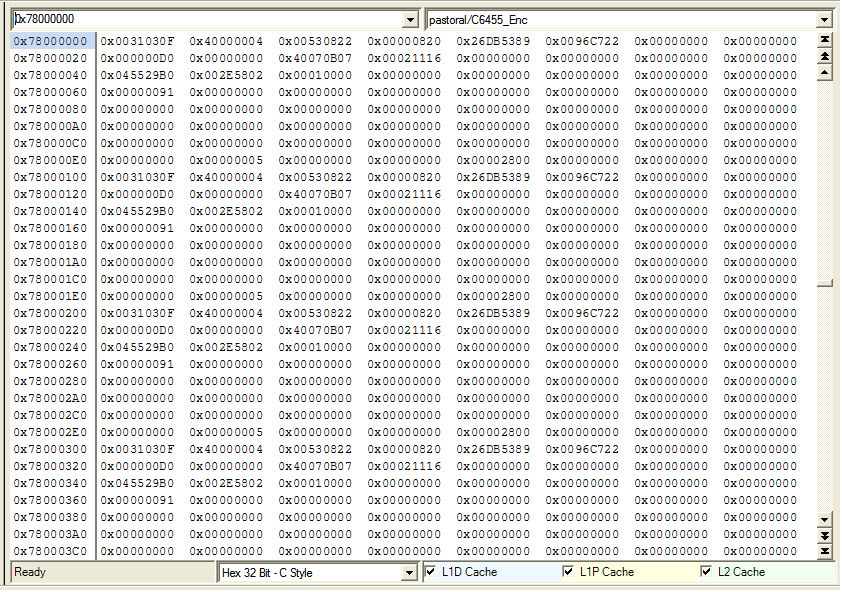
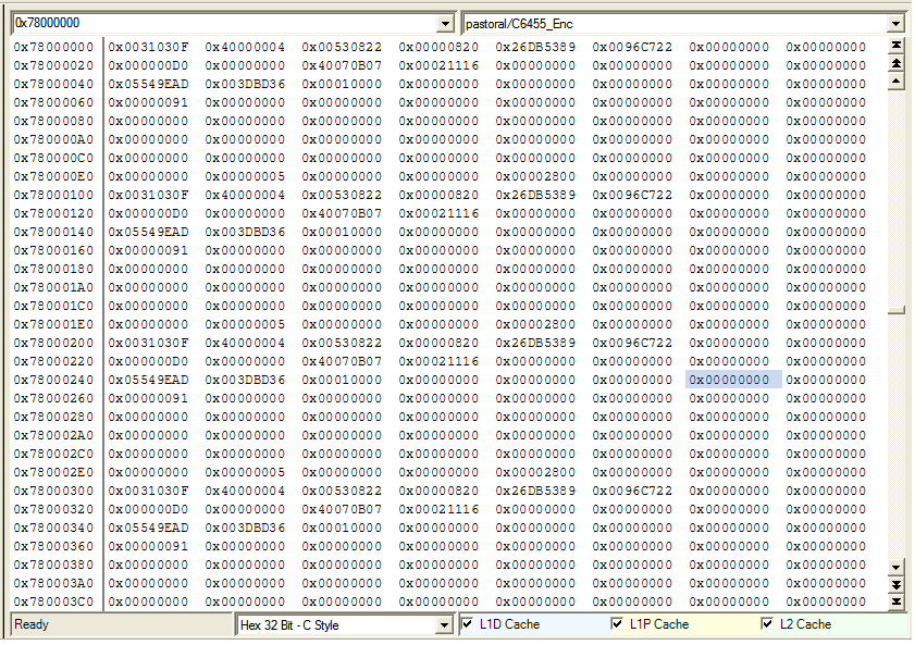
In short there seems to be memory errors when reading and writing to the DDR2 with L1D/L2D Cache enabled. ( usually a stuck bit ) Disabling the L2D cache ( or L1D Cache on some boards )gets rid of the memory problems. Please note this is a simple CPU driven read and write to external memory( no cache coherency issues ). The problem goes away after reset is applied again without power cycle.
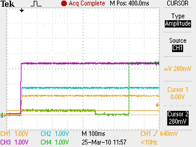
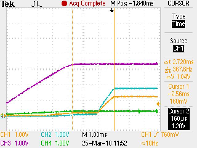
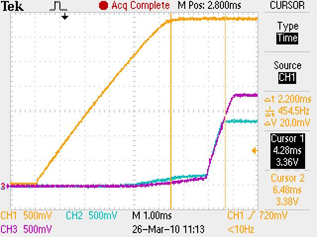
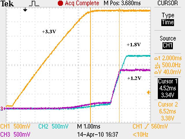
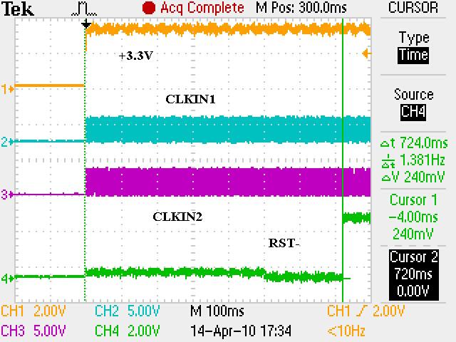
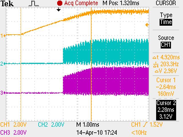
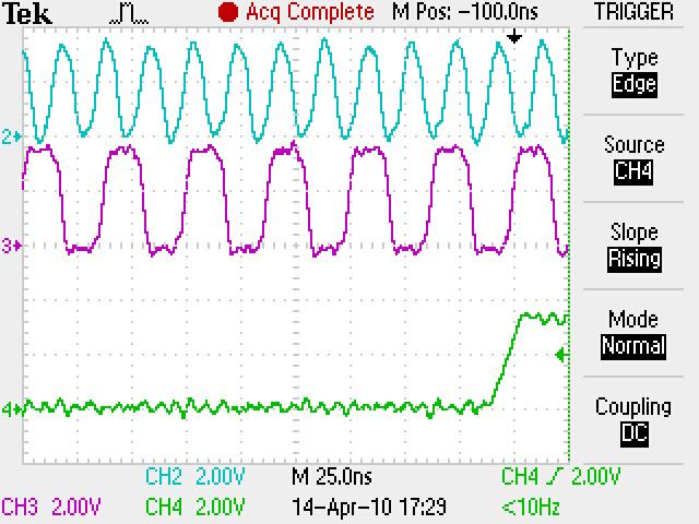
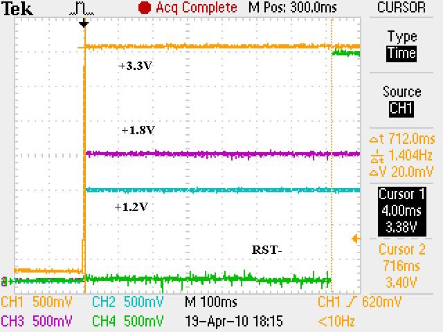
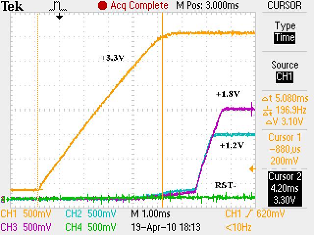
We have checked the power up and reset sequence, which complies with the datasheet requirement (3.3V first, then 1.2V and 1.8V together).
Delaying the reset deassertion after power is stable does not seem to make a difference.
Any suggestion? Anyone seen this kind of behavior before?

-
Ask a related question
What is a related question?A related question is a question created from another question. When the related question is created, it will be automatically linked to the original question.


