This thread has been locked.

If you have a related question, please click the "Ask a related question" button in the top right corner. The newly created question will be automatically linked to this question.

AM335x SPI overcurrent limit

Other Parts Discussed in Thread: AM3352, TXS0102

Hi,

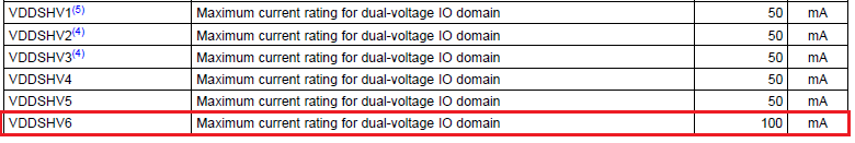
We would like to know if AM3352's SPI interface has overcurrent limit(Protection) in-built?
I couldn't find any such details on the datasheet, can I assume there is no protection?

We want to know what could happen if the SPI lines are stuck at HIGH/LOW levels.
In one of our customer's application we found that there is a possibility of short circuit on the SPI Bus
in some cases. So we would like to know what could happen in this case and if there is any in-built protection.


Best Regards
Kummi

  • Hi Kummi,

    AM335X I/O pins are not fail-safe. You should provide external current limitation in such cases.

  • Hi Biser,

    Thank you for very quick reply.
    Just in case please let me know if there is any SPI current limitation/control IC From TI..

    Best Regards
    Kummi
  • In my opinion some serial resistors should be enough.

  • Hi Biser,

    Thank you.

    Could you please let me know if there is any general guideline to
    select the value of series resistor. Will it be OK if we use 22 ohm series resistors.

    Best Regards
    Kummi
  • This would depend on the VDDSHVx voltage used - 1.8V or 3.3V. Please check also Table 5-10 in the AM335X Datasheet Rev. G for maximum current ratings on power supplies.

  • Hi Biser,

    Thank you for the information.
    Please let me clarify this, as there is no specification of
    maximum current for a pin in the datasheet.

    Regarding the maximum current in "Table 5-10",
    do you mean to say "Maximum current rating for dual-voltage IO domain"?

    The SPI0  belongs to VDDSHV6 power domain(100mA) & the voltage used is 3.3V.
    So can I assume the SPI over current should not exceed 100mA?

    And if we use 22 ohm series resistors on the SPI bus,
    the over-current may cross 150mA during short-circuit....
    So we may have to use atleast 33ohm resistors? to avoid the damage of the SPI pins.

    Please let me know if the above understanding is correct?

    Best Regards
    kummi

  • I have been thinking about this and maybe in your case the serial resistors may not be a good idea. As an alternative I would suggest using a level translator like TXS0102, which would limit the output current in a short condition.

  • Hi Biser,

    Thank you.

    Unfortunately we are into mass production in few days
    so series resistor is the quick option we could implement.

    If possible could you please let know what could be the implications
    if we choose to use the series resistor...
    and will be ok if we use a higher value like 100 ohm to 500 ohm?

    Your information is very much useful at this juncture.

    Best Regards
    Kummi

  • Which are the processor pins involved? And what is the normal input current on the other side of the SPI?

  • Hi Biser,

    The pins used are spi0_cs0,spi0_d0,spi0_d1,spi0_sclk to connect a SPI Flash.
    Actually two of AM3352 processors are conected to the same SPI Flash which
    needs 4mA Active current.

    Best Regards
  • I suppose you are talking about 4mA total current. Input current on the flash SPI pins should be in the range of microamps. SPI is not a multi-host interface, precautions should have been taken at the design phase. As for SPI0 pins, they can source/sink up to 6mA. You can try with something like 680 Ohm serial resistors (3.3V / 6mA = 550 Ohm).

  • Hi Biser,

    Thank you very much.This was very helpful.

    Yes the that was total current of SPI.
    We shall try with 680 Ohm series resistors.

    Best Regards
    kummi
  • Hi Kummi,

    A colleague has asked me to tell you that using too big resistor values could have negative effect on high frequency performance, so I guess that you would need to experiment a bit to find the right value that satisfies your needs.

  • Hi Biser,

    Thank you for the suggestion.
    We shall try to test with different resistor values.

    Meawhile, I am little bit confused about the "5.1 Absolute Maximum Ratings" mentioned in the datasheet.
    It mentions "Steady State Max. Voltage at all IO pins" is " -0.5V to IO supply voltage + 0.3 V".


    I believe apart from the SPI pins source/sink Max current(6mA) limitation,
    we should also take care about this point...i.e the SPI input voltage should not cross -0.5V to 3.6V.

    Please let me know if the above understing is correct.

    Best Regards
    Kummi

  • Kummi said:
    ...i.e the SPI input voltage should not cross -0.5V to 3.6V.

    Yes, this is absolutely correct.

    I would also like to clarify about the +/-6mA current, this is not limited inside the pin I/O buffer, actually the pin can deliver more than that, but pin voltage levels will change significantly. +/-6mA is specified for output high level = VDDSHx - 0.45V and output low level = 0.45V.

  • Kummi,

    The "Steady State Max. Voltage at all IO pins" parameter is related to a comment Biser mentioned in his first post. The SPI IOs are not fail-safe, which means this parameter applies when power is off, ramping up, or ramping down. For example, you must never source more than VDD + 0.3, which would be 0.3 volts, to these IOs when power is not applied to the AM335x device.

    Regards,
    Paul
  • Hi paul,

    Thank you.

    So the conclusion is that we should maintain the I/O voltage below "absolute maximum input voltage"
    under all the situation (power is off, ramping up, or ramping down).

    And during the active state we should maintain the current limitation(less than +/-6mA) to the SPI pins in our case.

    Best Regards
    Kummi
  • Hi Biser,

    I am really sorry for bothering you again.

    One clarification about your comment...
    You mentioned that "actually the pin can deliver more than that, but pin voltage levels will change significantly"

    So can we assume the SPI can source/sink current more than 6mA?
    We are confused because,without knowing the maximum current it would be difficult to choose
    the right series resistor. We wonder what current value would damage the SPI port.

    Best Regards
    kummi.
  • These IOs are able to source/sink more current than the AM335x device was designed to source or sink. That is why your product design must limit the current of all external loads to less than 6mA of sink/source current. These IOs are designed to source/sink LVCOMS loads which are small capacitive loads with a small amount of DC leakage. In some cases, there may be additional pull-up or pull-down resistors that present additional DC load. The total DC load shall always be less than 6mA.

    For example, if operating the IO at the maximum potential of 3.465 volts, the DC load to ground must be greater than 577.5 ohms.

    These IO were not designed to support a use case where they are shorted to VDD or VSS. The way you are trying to connect more than one processor directly to a single memory device is not a good design practice. Using series current limiting resistors as a way to protect the devices when may be a viable solution. However, there may be side effects. These resistors will slow transitions, which could cause the resultant signals to violate SPI timing parameters. If the signals have additional DC loads like pull-up/pull-down resistors, the DC voltage drop across the series resistors could cause the signals to violate Vih min and Vil max limits of respective input buffers.

    Regards,
    Paul

  • I made a mistake in my last post, which originally said the DC load must be less than 577.5 ohms. I should have said greater than 577.5 ohms.

    Subscribers to this thread may have gotten an email with this error. Please ignore the email version and refer to the updated reply on E2E.

    Regards,
    Paul
  • Thank you very much for the detailed information...This is very helpful!!