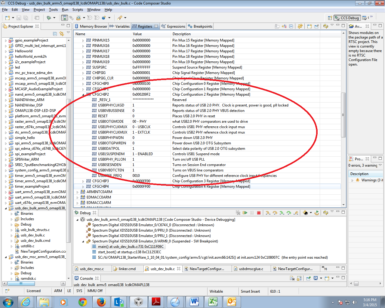
I have a custom build TMS320C6748 board. When using the bulk usb device example, it hangs on the line
while (!(HWREG(g_USBInstance[ulIndex].uiPHYConfigRegAddr) & CFGCHIP2_PHYCLKGD));
in usbphyGS60.c. The CFGCHIP2_PHYCLKGD value always is 131072 and uiPHYConfigRegAddr value always is 29442436 ,(The uartecho program works great).
What should I do?
Setting in AISgen:
Boot mode = UART0
Clock source = Oscillator @ 24 MHz
PLL0:
Pre-divisor = 1
Multiplier = 24
Post-Divisor = 2
DIV1 = 1
DIV3 = 3
DIV7 = 6
PLL1:
Multiplier = 20
Post-Divisor = 2
DIV1 = 1
DIV2 = 2
DIV3 = 3
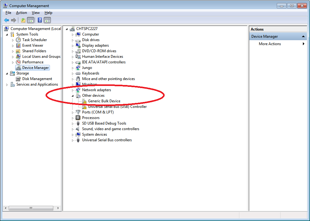
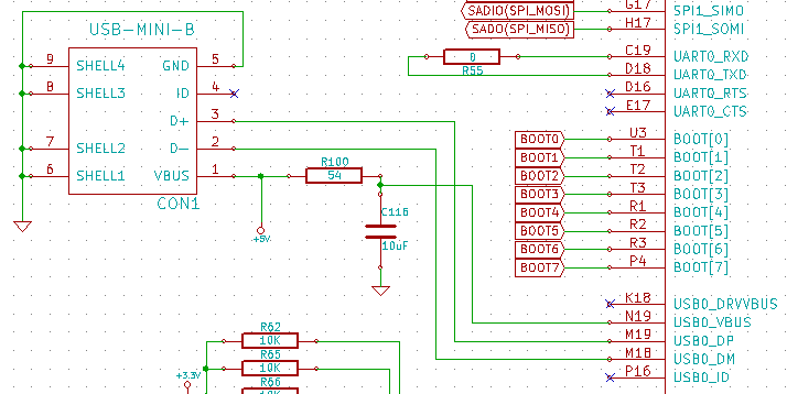
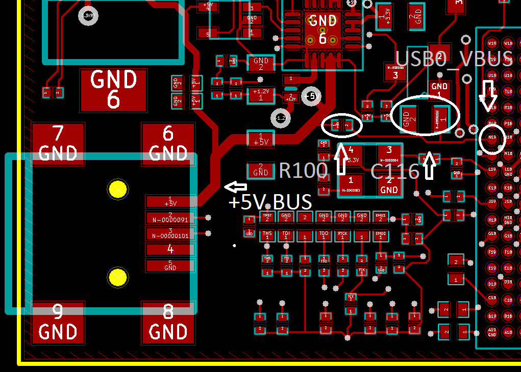
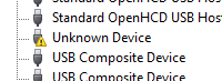
USB connection:
https://www.dropbox.com/s/279qpnp9hpuu803/Capture.PNG?dl=0