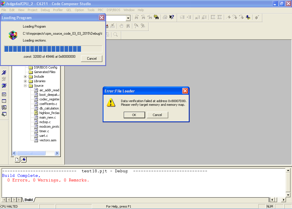
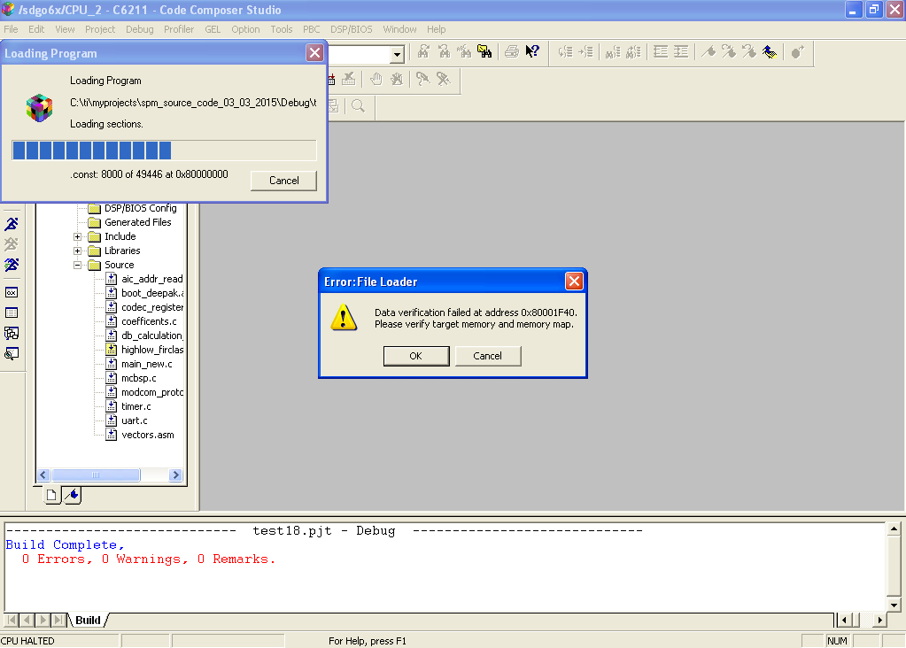
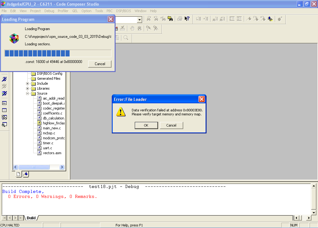
hai i am using 6211 based custom dsp board. In this interfaces the SDRAM. There are two booards with me. One is working fine. other has a problem when iam loading my project to the dsp, i get the following messages...
can anyone help me please?

This thread has been locked.
If you have a related question, please click the "Ask a related question" button in the top right corner. The newly created question will be automatically linked to this question.
hai i am using 6211 based custom dsp board. In this interfaces the SDRAM. There are two booards with me. One is working fine. other has a problem when iam loading my project to the dsp, i get the following messages...
can anyone help me please?

Hai sir,
I can reset emulator. I can load other small programs. Here i interfaced SDRAM with DSP through EMIF.
yes sir i am using internal RAM. But the program loading error message showing that problem in the SDRAM location 0x8000000. sir here i am attaching my .gel file and linker command file.
======================
.gel
======================
/* DSK6211_6711.gel (11.29.2000mld)
*
* This GEL file is loaded on the command line of Code Composer.
* It designed to be used with Code Composer Studio 2.00 in
* conjunction with a 6211 or 6711 DSK.
*/
/*
* New GEL commands for 2.00
***********************************************************************
* OnPreFileLoaded()
* If defined, this is executed before all file loads
*
* OnFileLoaded(int nErrorCode, int bSymbolsOnly)
* If defined, this is executed after all file loads
*
* OnReset(int nErrorCode)
* If defined, this is executed after "Reset DSP'
*
* OnRestart(int nErrorCode)
* If defined, this is executed after "Restart'
***********************************************************************
*/
/*
* The StartUp() function is called every time you start Code Composer.
* You can customize this function to perform desired initialization.
* This function may be comment out if no initialization is needed.
*/
StartUp()
{
setup_memory_map();
GEL_Reset();
init_emif();
}
/*
* Initialize the EMIF. This will set up the EMIF and read the
* board configuration to ascertain the memory size/geometry and
* set it up accordingly.
*/
init_emif()
{
/*
* First we define the EMIF addresses
*/
#define EMIF_GCTL 0x01800000
#define EMIF_CE1 0x01800004
#define EMIF_CE0 0x01800008
#define EMIF_CE2 0x01800010
#define EMIF_CE3 0x01800014
#define EMIF_SDRAMCTL 0x01800018
#define EMIF_SDRAMTIMING 0x0180001C
#define EMIF_SDRAMEXT 0x01800020
#define EMIF_CCFG 0x01840000; /*Cache configuration register*/
/*
* Now we set the values
*/
*(int *)EMIF_GCTL = 0x00003300; /* EMIF global control register */
*(int *)EMIF_CE0 = 0x00000030; /* CE0-SDRAM */
*(int *)EMIF_CE2 = 0xFFFFFF23; /* CE2-32bit async on daughtercard*/
*(int *)EMIF_CE3 = 0xFFFFFF23; /* CE3-32bit async on daughtercard*/
*(int *)EMIF_SDRAMCTL = 0x07227000; /* SDRAM control register(100 MHz)*/
*(int *)EMIF_SDRAMTIMING = 0x0000061A; /* SDRAM Timing register */
*(int *)EMIF_SDRAMEXT = 0x00054529; /* SDRAM Extension register */
/*
* LED setup define some LEDs for user feedback
* Note that each LED1-3 command turns off all of the other LEDs
*/
#define LED1_on *(int *)0x90080000 = 0x0E000000
#define LED2_on *(int *)0x90080000 = 0x0D000000
#define LED3_on *(int *)0x90080000 = 0x0B000000
#define LEDs_off *(int *)0x90080000 = 0x07000000
/* #define CE1_32bit
* CE1 - Force 32-bit asynch access mode - this mode is required to
* read dip switches or board configuration
*/
#define CE1_32bit *(int *)0x01800004 = 0xFFFFFF23
/* #define Get_Board_Rev
* This reads IO port
* shifts the revision to low 3 bits
* and masks off everything else
*/
#define Get_Board_Rev ((*(int *)0x90080000>>29) & 0x07)
/* #define Get_Switches
* This reads IO port
* shifts the switches to low 3 bits
* and masks off everything else
*/
#define Get_Switches ((*(int *)0x90080000>>24) & 0x07)
/*--------------------------------------------------------------------*/
/* Modify SDRAM parameter value(s) according to board revision */
/*--------------------------------------------------------------------*/
/*************************************************************************
* Standard 6211 DSK includes 2 MT48LC1M16A1-7 devices =>4MB SDRAM *
* 16Mb (16-bit x 2 banks x 512K) parts = 2MB / part *
* EMIF_SDCTRL=0x07227000 *
* EMIF_SDEXT=0x54529 Board Rev = 1 *
*------------------------------------------------------------------------*
* Standard 6711 DSK includes 2 MT48LC4M16A2-8 devices =>16MB SDRAM *
* 64Mb (16-bit x 4 banks x 1M) parts = 8MB / part *
* EMIF_SDCTRL=0x57116000 *
* EMIF_SDEXT=0x54529 (Hitachi 0x54509) Board Rev = 2 *
*------------------------------------------------------------------------*
* Other 6711 DSK configurations are as follows: *
* 128Mb (16-bit x 4 banks x 2M) parts = 16MB / part (=>32MB SDRAM) *
* EMIF_SDCTRL=0x53116000 *
* EMIF_SDEXT=0x54529 (Hitachi 0x54509) Board Rev = 3 *
* ---------------------------------------------------------------------*
* 256Mb (16-bit x 4 banks x 4M) parts = 32MB / part (=>64MB SDRAM) *
* EMIF_SDCTRL=0x63116000 *
* EMIF_SDEXT=0x54529 Board Rev = 4 *
*************************************************************************/
/* Check for board revision match
* If board revision match is detected
* set 'CE1_32bit' to ensure the correct mode
* flash the revision number in the LEDs
* write the correct value to 'EMIF_SDRAMCTL'
* If board revision match is NOT detected
* open a window
* print a warning message
*/
/*6211 DSK 16 Mb RAM*/
if(Get_Board_Rev == 1)
{
CE1_32bit;
LED1_on;
*(int *)EMIF_SDRAMCTL = 0x07227000;
LEDs_off;
}
/*6711 DSK 64Mb RAM*/
if(Get_Board_Rev == 2)
{
CE1_32bit;
LED2_on;
*(int *)EMIF_SDRAMCTL = 0x57116000;
LEDs_off;
}
/*6711 DSK 128Mb RAM*/
if(Get_Board_Rev == 3)
{
CE1_32bit;
LED1_on;
LED2_on;
*(int *)EMIF_SDRAMCTL = 0x53116000;
LEDs_off;
}
/*6711 DSK 256Mb RAM*/
if(Get_Board_Rev == 4)
{
CE1_32bit;
LED3_on;
*(int *)EMIF_SDRAMCTL = 0x63116000;
LEDs_off;
}
/*We don't know how to init this revision*/
if(Get_Board_Rev > 4)
{
GEL_OpenWindow("Fred", 0, 5);
CE1_32bit;
GEL_TextOut(" Switches: %d Revision: %d\n\n","Fred",1,1,1,
Get_Switches, Get_Board_Rev);
GEL_TextOut("**** Warning Board NOT recognized!! *****\n","Fred",2,1,1);
GEL_TextOut("**** Warning EMIF NOT Configured!! *****\n","Fred",1,1,1);
}
}
/*
* Clear the memory map settings
*/
clear_memory_map()
{
GEL_MapOff();
}
/*
* Setup the memory map for the C6211 DSK
*/
setup_memory_map()
{
/* Enable memory mapping in Code Composer */
GEL_MapOn();
/* Reset all memory to unreadable and unwritable */
GEL_MapReset();
/* Syntax for GEL_MapAdd(address, page, length, readable, writeable)
* page: Program Memory = 0, Data Memory = 1, I/O Space = 2
* readable: Not Readable = 0, Readable = 1
* writeable: Not Writeable = 0, Writeable = 1
*/
/* C6211 DSK-specific memory mapping */
/*--------------------------------------------------------------------*/
GEL_MapAdd(0x00000000,0,0x00010000,1,1); /* Internal RAM (L2) mem */
GEL_MapAdd(0x01800000,0,0x00000024,1,1); /* EMIF control regs */
GEL_MapAdd(0x01840000,0,0x00000004,1,1); /* Cache configuration reg */
GEL_MapAdd(0x01844000,0,0x00000020,1,1); /* L2 base addr & count regs*/
GEL_MapAdd(0x01844020,0,0x00000020,1,1); /* L1 base addr & count regs*/
GEL_MapAdd(0x01845000,0,0x00000008,1,1); /* L2 flush & clean regs */
GEL_MapAdd(0x01848200,0,0x00000010,1,1); /* CE0 mem attribute regs */
GEL_MapAdd(0x01848240,0,0x00000010,1,1); /* CE1 mem attribute regs */
GEL_MapAdd(0x01848280,0,0x00000010,1,1); /* CE2 mem attribute regs */
GEL_MapAdd(0x018482c0,0,0x00000010,1,1); /* CE3 mem attribute regs */
GEL_MapAdd(0x01880000,0,0x00000004,1,1); /* HPI control reg */
GEL_MapAdd(0x018c0000,0,0x00000028,1,1); /* McBSP0 regs */
GEL_MapAdd(0x01900000,0,0x00000028,1,1); /* McBSP1 regs */
GEL_MapAdd(0x01940000,0,0x0000000c,1,1); /* Timer0 regs */
GEL_MapAdd(0x01980000,0,0x0000000c,1,1); /* Timer1 regs */
GEL_MapAdd(0x019c0000,0,0x0000000c,1,1); /* Interrupt selector regs */
GEL_MapAdd(0x01a00000,0,0x00000800,1,1); /* EDMA parameter RAM */
GEL_MapAdd(0x01a0ffe0,0,0x00000020,1,1); /* EDMA control regs */
GEL_MapAdd(0x01bc0000,0,0x00000050,1,1); /********cTools*********/
GEL_MapAdd(0x02000000,0,0x00000014,0,1); /* QDMA regs */
GEL_MapAdd(0x02000020,0,0x00000014,0,1); /* QDMA pseudo-regs */
GEL_MapAdd(0x30000000,0,0x04000000,1,1); /* McBSP0 data */
GEL_MapAdd(0x34000000,0,0x04000000,1,1); /* McBSP1 data */
GEL_MapAdd(0x80000000,0,0x01000000,1,1); /* CE0, SDRAM, 16 MBytes */
GEL_MapAdd(0x90000000,0,0x00020000,1,1); /* CE1, 8-bit ROM, 128KBytes*/
GEL_MapAdd(0x90080000,0,0x00000004,1,1); /* CE1, 8-bit I/O port */
GEL_MapAdd(0xA0000000,0,0x10000000,1,1); /* CE2 - Daughtercard */
GEL_MapAdd(0xB0000000,0,0x10000000,1,1); /* CE3 - Daughtercard */
}
/***********************************************/
LED_cycle()
{
LED3_on;
LED2_on;
LED1_on;
LED2_on;
LED3_on;
LEDs_off;
}
/*
This function is called automatically when the 'Reset DSP'
Menu item is selected .....
*/
OnReset(int nErrorCode)
{
CE1_32bit;
LED3_on;
LED2_on;
LED1_on;
FlushCache();
init_emif();
LEDs_off;
}
/*
* OnPreFileLoaded()
* This function is called automatically when the 'Load Program'
* Menu item is selected .....
*/
OnPreFileLoaded()
{
CE1_32bit;
LED2_on; /*Flash LED for Visual Indication Only*/
FlushCache();
LEDs_off;
}
/*
* FlushCache()
* Actually Invalidate L1D and L1P, Internal RAM
*/
FlushCache()
{
LED1_on;
LED2_on;
LED3_on;
*(int *)0x01840000 = (*(int *)0x01840000 | 0x00000300);
LEDs_off;
}
ReadRev_and_Switches()
{
GEL_OpenWindow("Fred", 0, 5);
CE1_32bit;
GEL_TextOut(" Switches: %d Revision: %d\n\n","Fred",1,1,1,
Get_Switches, Get_Board_Rev);
GEL_TextOut("*****Target is Okay *******\n","Fred",2,1,1);
}
/*
* The 'menuitems' below will appear on the CCS GEL menu
* The 'hotmenu' functions define executeable 'sub-menuitems'
* for the 'menuitems'
*/
/*
* Not Required
*
********************************************************
menuitem "Resets";
hotmenu Reset_BreakPts_and_EMIF()
{
GEL_BreakPtReset();
GEL_Reset();
init_emif();
}
Flush_Cache forces L1D and L1I to be invalidated
hotmenu Flush_Cache()
{
FlushCache();
}
*
********************************************************
*/
menuitem "Memory Map";
hotmenu SetMemoryMap()
{
setup_memory_map();
}
hotmenu ClearMemoryMap()
{
clear_memory_map();
}
menuitem "Check DSK";
/*
* QuickTest verifies communication with the target peripherals
* The following must function for QuickTest to print the board
* revision and switch configuration:
***Output Path***
* CCS[sw]->emulation driver[sw]->parallel port adapter[sw]->
* PC parallel port[hw]->parallel port cable[hw]->
* dsk parallel port controller[hw]->dsk Test bus Controller[hw]->
* JTAG[hw[->6X11 DSP[hw]->external latch[hw]->LEDs
***Input Path***
* Dip Switches & Revision info->6X11 DSP->JTAG->
* dsk Test Bus Controller->dsk parallel port controller->
* parallel port cable->PC parallel port->parallel port adapter->
* emulation driver->CCS
* If we traversed the output and input paths correctly we should
* have a GEL output window open with the following information
* [the numeric values will vary depending on the actual switch
* setting and board revision]:
Switches: 5 Revision: 2
*****Target is Okay *******
*/
hotmenu QuickTest()
{
CE1_32bit;
LED_cycle();
LED_cycle();
LED_cycle();
ReadRev_and_Switches();
}
========================================
.cmd file
========================================
-l rts6201.lib
-l csl6211.lib
-heap 0x2000
-stack 0x800
MEMORY
{
BOOT_RAM o = 00000000h l = 00400h /* reset & interrupt vectors */
IRAM: o = 00000400h l = 0FC00h /* intended for initialization */
SDRAM: o = 0x80000000 l = 0x0100000 /* .bss, .sysmem, .stack, .cinit */
}
SECTIONS
{
.boot_load > BOOT_RAM
.vectors > IRAM
.text > IRAM
.bss > IRAM
.switch > IRAM
.tables > IRAM
.data > IRAM
.stack > IRAM
.sysmem > IRAM
.cinit > IRAM
.const > SDRAM
.pinit > IRAM
.cio > IRAM
.far > SDRAM
}

Hi Rakesh,
I can run simple led program on SDRAM. I can write to and read from SDRAM location.
I can view the SDRAM location through CCS.
Hai sir,
In our board dsp and sn74lvth32374 are a BGA ICs. we have mounted the BGAs from outside and mounted the other components by our own. We mounted the components for two boards. One board is working fine. Other has problems. I checked the SDRAM signals for read and write for the boards. Both are showing the same.
is this the problem with BGA IC mounting?
in that case how this works for smaller programs?
No sir , I don't have EVM board.
thanks and regards,
Rakesh T