This thread has been locked.

If you have a related question, please click the "Ask a related question" button in the top right corner. The newly created question will be automatically linked to this question.

AM3352 ZCE and USB2512 HUB connection

Other Parts Discussed in Thread: AM3352

Hi everybody,

I'm working on hardware design of custom am3352 based device. AM3352 is in ZCE package. Because the processor doesn't have enough USB ports I decide to use USB2512 USB hub and connect it to the processor to get one more USB port. I found that USB on AM3352 is OTG port which means that it can be either HOST or Device. Selection between HOST and device is done by pulling up or down ID pin of the processor. I connected the USB0_ID via zero ohm resistor to the GND and configure the port to always be a HOST. USB_DP and USB_DM are connected to the proper pins of USB2512 HUB.

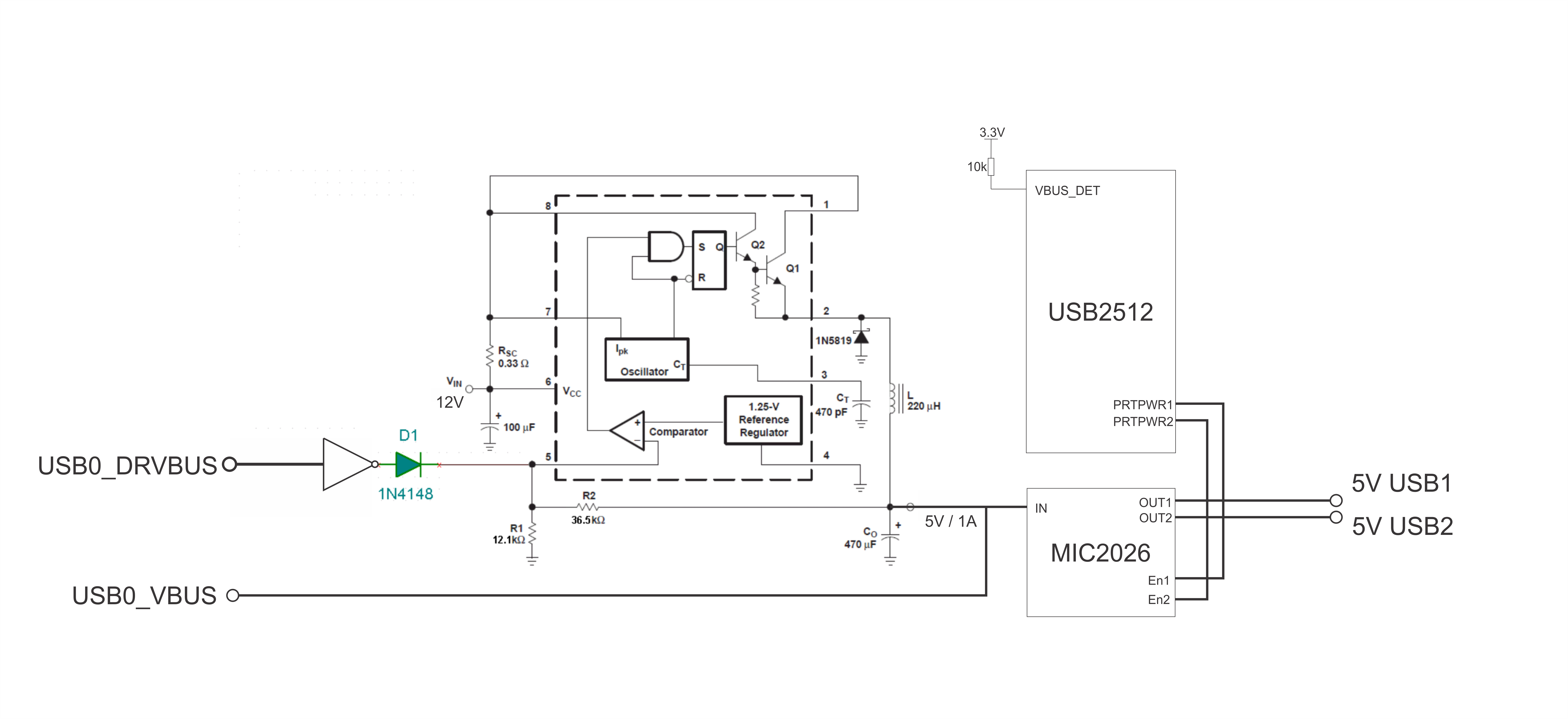
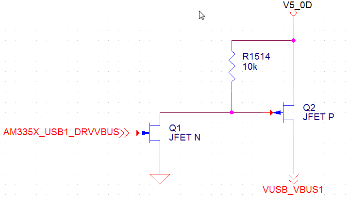
Only thing I didn't understand is where to connect USB0_DRVBUS and USB0_VBUS.

1) I think that I don't need to use USB0_DRVBUS because the USB2512 have own bus voltage enable pins.

2) Because I 'm using USB0 always as HOST I think that USB_VBUS have to be connected to the 5V to power USB controller, am I right? 

Also USB0_CE is not necesary for HOST if I understand right?

I can update schematic if someboty is need it.

Best regards.

  • Hi Miroslav,

    Please check this wiki: http://processors.wiki.ti.com/index.php/AM335x_Schematic_Checklist#USB There is a section describing typical connections for a USB host with USB hub. About USB0_CE your understanding is right, you can leave it floating.

  • Thank you very much, I checked the Wiki page. In datasheet of USB2512 I found that "For self powered applications with a permanently attached host, VBUS_DET pin must be connected to 3.3V". I'm planing to use MC33064 to generate 5V for USB port power. I made circuit to enable/disable power supply with MC34063. In that case I will do next:

    1) Connect AM3352_USB0_DRVBUS to the Enable disable pin of MC340633 circuit.

    2) Connect OUTPUT of MC34063 circuit to the AM3352_USB0_VBUS and to the input of MIC2026_INPUT.

    3) USB2512_VBUS_DET is connected via 10k resistor to the 3.3V as is suggested in datasheet.

    4) USB2512_DRVBUS pins are used to control MIC2026 OUTPUTS and to enable or disable BUS power.

    I attached simple block diagram to explain my idea.

    Please correct me if I'm wrong.

    Best regards. 

  • I'm not sure how the USB0_DRVVBUS circuit will work. USB0_DRVVBUS is active high, with high level 1.8V or 3.3V, depending on VDDSHV6 voltage used. Also I'm not sure what the MC340633 ramp-up/down time is. As an alternative you could have it always turned on and use a simple circuit like this:

  • OK, I agree with you, because it is DC/DC converter its need some time to stabilize. The idea which you gave me is better than go to directly from MC34063 to the USB_VBUS.

    Everything is clear now, thank you very much again for your help.