This thread has been locked.

If you have a related question, please click the "Ask a related question" button in the top right corner. The newly created question will be automatically linked to this question.

BT656 timing @ DM365

Other Parts Discussed in Thread: TVP5146

Hi,

what ISIF and IPIPEIF register do I have to set when using a camera in 8bit BT656 mode?

I know the REC656IF register in ISIF, and also the 8bit per pixel pack mode etc. But I am not sure about HD/VD/FLD polarities in both ISIF and IPIPEIF. I also can't find out if I should set the internal HD/VD timing generator register in ISIF (PPLN, LPFR and MODSET.HDVDD).

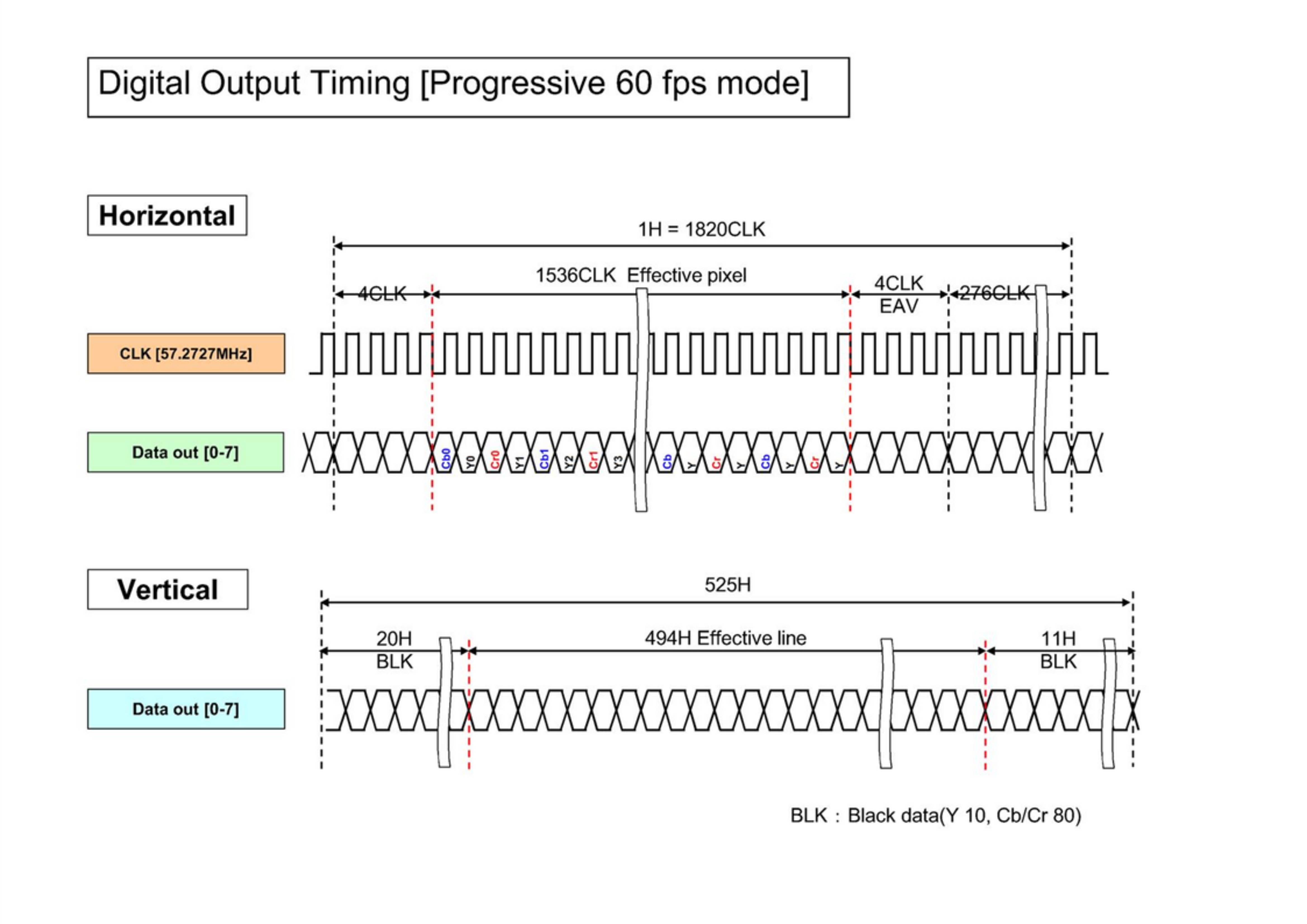
I am also attaching the BT656 timing of my camera to this post.

I would appreciate some more information regarding BT656 input and/or an example register setting.

Thank you.

Sebastian

  • Please refer to linux-2.6.18_pro500/drivers/media/video/davinci/ccdc_dm365.c, the register settings is mostly in function ccdc_config_ycbcr().

  • Hi Sebastian,

    As you rightly pointed out, REC656IF is the register that needs to be set. For HD/VD/FLD, you should keep it as input. Also PPLN, LPFR etc are not needed to be set. Anyways, it will be calculated based on embedded sync inside ISIF.

    Please refer to the section "ITU-R BT.656/ 1120 4:2:2 Parallel Interface" in VPFE user guide for more details.

    What exactly is the problem you are facing with these settings?

    Regards,

    Anshuman

  • Hi Anshuman,

    thank you for the reply. I read the user guide carefully again, but I could't find a fault in my settings. My program is actually a modified version of the function "static int ccdc_config_ycbcr(int mode)" from the file "dm365_ccdc.c".

    To be sure that the transmitter is working, I connected a TVP5146 chip to the VPFE. The data is transfered and displayed correctly in YCbCr 8bit mode with external syncs, but switching to BT656 results in no data inside my framebuffer.

    So I know that data gets through (from extarnal sync mode) but on the other hand, BT656 mode is just not working at all.

    My guess was that the DM365 is not handling SAV and EAV timings correctly due to a fault register setting. I noticed that in the function "static int ccdc_config_ycbcr(int mode)" the VD polarity is switched to negative when in BT656 mode, but there is no comment to that in the VPFE user guide.

    Thus the guy who wrote the LSP knew something I don't. What about you Anshuman, what do you know about the sync signals generated by the BT656 decoder?

    Regards

    Sebastian


  • Hi Sebastian,

    Here are my settings for BT656 configuration. Please ignore the sizes of frame as in my case, i am trying a different frame size. But all other control parameter registers are something you can refer. Ofcourse in my case also, the polarity of VD is negative. I am looking at the exact reason of why we left it to negative. Did you already try to set VD polarity as negative and test?

    BTW, when you are saying, you dont get any data in your output buffer, are you sure you are getting the interrupts and your DQ_BUF IOCTL of V4L2 is passing successfully. One reason of not getting the interrupt which in turns mean DQ_BUF not succeeding is the setting of your VD0INT and VD1INT register.


     0x01c71000: 00000003 00002004 00000000 00000000
     0x01c71010: 00000000 00000001 00000000 000005af
     0x01c71020: 00000000 00000000 00000833 0000ffff
     0x01c71030: 000000ff 0000002e 00000000 00000423
     0x01c71040: 00006400 00000000 00000000 00000000
     0x01c71050: 00000200 00000200 00000200 00000200
     0x01c71060: 00000000 00000000 00000000 00000000
     0x01c71070: 000007ee 000007ee 000007ee 00000000
     0x01c71080: 00000000 00000001 00008802 00000000


    Regards,

    Anshuman

  • Hi Sebastian,

    I cross checked again after changing polarity of VD to Positive. Either case, it does not make any impact to the captured data. We had left it as Negative based on the LSP driver code.


    Regards,

    Anshuman

  • Hi Anshuman,

    thanks you for your register settings. I cross checked them with mine and everything with my settings seems to be ok. I noticed that you have enabled CCDCFG.VDLC and CCDCFG.Y8POS. I tried that too, but got no result.

    Just to be sure I understand the register right:

    (1) Your LNH register is 0x5af, which sets your valid pixel-clock-count to 1455+1, which means in YCC8 mode 728 horizontal 16bit pixel per line.

    (2) The LNV register is 0x833, which sets a vertical resolution of 2099+1 lines per frame.

    Is it right that your camera or at least your output window has a resolution of 728x2100 pixel?

    (3) You haven't activated CCDCFG.YCINSWP, which means that you have connected your data lines to CIN[7..0].

    My other register settings are the same as yours (except CADU/L). Maybe we can find a difference in the IPIPE/IF settings. I would appreciate if you post these too.

    Well, back to my module. It only has one framebuffer which both VPFE and VPBE are accessing. A lot of tearing but no interrupt handling for now. And as I already mentioned, everything works fine with external syncs.

    What I find very confusing is that ISIF isn't putting a single byte to the designated framebuffer. Shouldn't ISIF start writing as soon as the first embedded sync has reached the BT656 decoder?

    I am looking forward to hear from you again,

    Sebastian

  • Hi Sebastian,

    Sebastian Kruber said:

    (1) Your LNH register is 0x5af, which sets your valid pixel-clock-count to 1455+1, which means in YCC8 mode 728 horizontal 16bit pixel per line.

    (2) The LNV register is 0x833, which sets a vertical resolution of 2099+1 lines per frame.

    Is it right that your camera or at least your output window has a resolution of 728x2100 pixel?

    You are right. My settings were for multichannel analog capture from a decoder which gives 728x2100 frame size.


    Sebastian Kruber said:

    (3) You haven't activated CCDCFG.YCINSWP, which means that you have connected your data lines to CIN[7..0].

    My other register settings are the same as yours (except CADU/L). Maybe we can find a difference in the IPIPE/IF settings. I would appreciate if you post these too.

    Why do you say that YCINSWP is needed? I have connected my 8 bit data to YIN lines and the description of YCINSWP justifies my register setting and hardware connections.

    The CADU/L are for the DDR addresses and would be different between my setting and yours.


    One point of suspicion can be the SDOFST register settings. Those are responsible for the output data formatter. You might want to focus a little bit on them too.

    I have put my IPIPEIF settings also. Please do not worry about the sizes though. Because i divide my big 728x2100 frame to many smaller frames. But i checked the data in ISIF and i get the data. So there has to be some other problem going somewhere else. Are you sure about the data buffers? Can you fill them with some pattern and then see if it is getting overwritten or still holds junk data?

    Regards,

    Anshuman

     0x01c71200: 00000000 0000040d 000002e0 00000100
     0x01c71210: 000002d0 000000f0 0000041e 0000002e
     0x01c71220: 0000005c 00000010 00000200 00000006
     0x01c71230: 00000000 00000000 00000fff 00000000
     0x01c71240: 00000953 00000000 00000000 00000000
     0x01c71250: 00000fff 00000010 00000000 00000000
     0x01c71260: 00000000 00000000 00000000 00000000


  • YCINSWP is NEEDED when 8 bit data is connected to YIN lines.


    > Why do you say that YCINSWP is needed? I have connected my 8 bit data to YIN lines and the description of YCINSWP justifies my register setting and hardware connections.

  • Hi,

    Confirmed with the owner of the IP that YCINSWP is indeed NEEDED to be set to 1, when 8 bit YUV data is connected to YIN lines. Sorry for the confusion caused earlier.

    Regards,

    Anshuman

    PS: Please mark the post as verified, if you think it has answered your question. Thanks.