This thread has been locked.

If you have a related question, please click the "Ask a related question" button in the top right corner. The newly created question will be automatically linked to this question.

OMAP-L138 NOR Flash Writer on Custom Hardware

Other Parts Discussed in Thread: OMAP-L138, OMAPL138

Dear forum!

I have a custom hardware platform with an OMAP-L138, a 32MB DDR2, and a 32MB NOR flash. Im using the setup shown below:

  • Windows 7, 64bit
  • XDS100v2 style emulator (from OPELLA)
  • CCSv4 (4.1.1.00014)
  • 20MHz input quarz on my board

Ive been able to connect to the device (in debug), program the DSP to make LEDs blink and configure a eHRPWM controller. I modified the OMAP138_ARM.gel file to match my clock and DDR2 settings, which seems to work, because I can connect to the ARM core and fill the section of memory specified for DDR (starting at 0xC00000000).

Now, I am trying to get my flash up and running. My real goal here is to flash an image into my NOR flash so that I can boot from there, so Im trying to carry out the procedures on Flashing images to NOR Flash on on this page:

http://processors.wiki.ti.com/index.php/GSG:_DA8x/OMAP-L1/AM1x_DVEVM_Additional_Procedures#Flashing_images_to_NOR_Flash

Everything works fine: loading the gel file, running the NOR pinmux script, building the flash writer (norflash-writer.out). But when I run the NOR flash programmer, although it seems to work (no errors), I am not prompted for the input file, and nothing appears on the screen. When I halt the processor, the program counter is just hanging out at

address: 0xFFFD4664, data at address:   EAFFFFFE

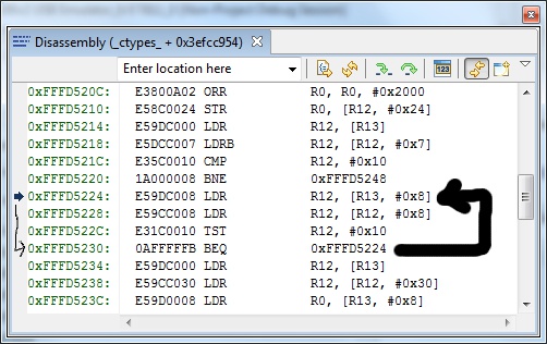
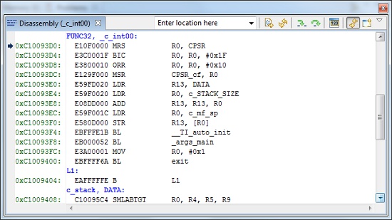
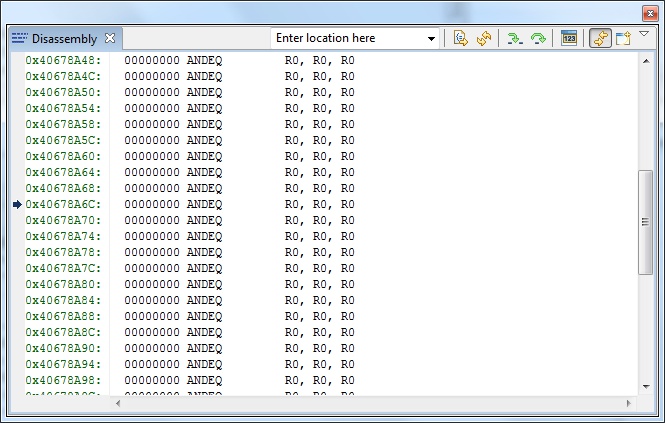
Initially, when I load the program and step through it, it seems to have loaded at the right address in the DDR2 (pic below), and stepping through it seems to work, until the processor starts into some long loop that I cant step out of (pic below). If I then let the program run, ends up at some random location (pic below).

Pic of disassembly after program load:
Pic of disassembly at loop: (after stepping it a while the labels seemed to jump , ie c16)

Pic of program ending up at a random location:
I know that this NOR flasher program was written for the Logic PD EVM, but I dont understand why Im not getting any printf messages on the console - at least this much should work without modifying the program to match my flash. I tried the exact same thing on the Logic PD Experimenter (with my OPELLA XDS100v2 emulator) and messages came up on the console.

Im going to post my modified GEL file. Any ideas what could be going wrong here?

  • Che,

    Are you able to load and debug the NOR writer code through CCS?  If you can set a breakpoint at main() and step through the code, it should help to identify what is going wrong.

    -Tommy

  • Hi Tommy,

    thanks for your reply. I did as you suggested and set up the NOR writer as a debug project in CCS. When I step through the code, it seems like random things are happening - the program counter will seemingly at random jump to a new address, and the data at some addresses seems to change at random. Any idea what might be going on here?

    Left: original program     Right: changed program after stepping

    Heres another version of that pic where ive highlighted some of the likely ways that the program changes

    Thanks and Cheers!  Che

  • Che,

    When you ran your DSP-side LED blink test, was it executed out of internal memory?  Can you try to execute that same test out of DDR?

    I'm worried that the DDR may not be stable so it will appear as if the contents are moving or changing randomly.

    -Tommy

  • I havent yet done what you've suggested, Tommy, but Ive got some other interesting clues. It turns out that one major problem was caused by my clock settings. After doing a bit more research, I determined that there are 2 clocks needed by the OMAPL138's DDR controller (from sprugm7c.pdf):

    1. the VCLK which comes from PLL0_SYSCLK2 (I think there is an error in sprugm7c.pdf that says VCLK is PLL0_SYSCLK2/2 when what is actually meant is that PLL0_SYSCLK2 has a fixed division ratio of 2). This clk should be set to half the DDR frequency: in my case 150MHz.
    2. the 2X_CLK which is sourced by PLL1_SYSCLK1 and should be set to the DDR frequency: 300MHz.

    I had PLL1_SYSCLK1 set at 150MHz, and I changed it to 300MHz. Here are my PLL settings for reference from my custom gel file (input oscillator 20MHz)

     //usage --> device_PLL0(CLKMODE, PLLM-1, POSTDIV-1, PLLDIV1-1, PLLDIV2-1, PLLDIV3-1, PLLDIV7-1)

    Set_Core_300MHz() {
        device_PLL0(0,29,1,0,1,11,5);
        GEL_TextOut("\tPLL0 init done for Core:300MHz, EMIFA:25MHz\n","Output",1,1,1);}

     //usage --> device_PLL1(PLLM-1,POSTDIV-1,PLLDIV1-1,PLLDIV2-1,PLLDIV3-1)

     Set_DDRPLL_150MHz() {
        device_PLL1(29,1,0,1,5); //was (29,3,0,1,2)
        GEL_TextOut("\tPLL1 init done for DDR:150MHz\n","Output",1,1,1);}

    After changing this, the issue with the shifting DDR2 data has gone away. I can now step through the program no problem.

    BUT! the program still doesnt work! It doesn't seem to make it through the auto initiation routine beginning at the label c_int00 and then branching to __TI_auto_init. What is this anyway? As far as I can tell it is part of the DSP/BIOS stuff that initializes system pointers, etc. a la TMS320 DSP/BIOS v5.41 User’s Guide spru423h.pdf, but Im not sure why or how it is getting inserted into my code, though I dont doubt that its necessary for operation (is there something in the .gel file that indicates this, or is this an automatic part of program build which is specified using Properties >> CCS Build >> Code generation tools: TI v4.6.1?)

    Here is the problem:

    1. I cant seem to come across any problems at all by stepping through the code,
    2. whenever I set a breakpoint in the code to see if and when the PC gets there, I get an error: ARM9_0: Trouble Reading Memory Block at 0xc1003b50 on Page 0 of Length 0xe5: 0x00000004/-2030 @ marker 1026 Error during: Register,  Access to an unknown or invalid register was attempted.(by the way, I dont get this error when I do the same thing using LogicPD's Experimenter board)
    3. if i just let the program run, it doesnt seem to make it to main() to do the printf, but rather ends up in an infinite loop at 0xFFFD5224, see pic below. Maybe its meaningful that this is in the ARM Local ROM??? It seems like it is looking/testing/waiting for something to happen that never does.

    When I run the same program from shared RAM it works and messages are printed on the console (altering the linker command file). When I run the program on the Experimenter board it works (using the gel file from LogicPD).

    Ill try running my DSP program from DDR2 and get back to you!

    Thanks again for your help - Che


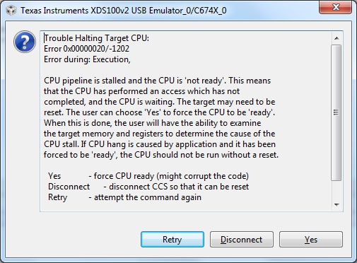
  • OK, just tried out my LED blink program in the DDR2 (which was running from internal mem), and the result is: didnt work. I run the program and nothing happens, and when I try to halt the CPU i get this error:

    So there is obviously something up with the DDR2 here. But is the chip compromised, is my board bad, or are my OMAP settings just bad? Hmm.... debugging suggestions, anyone... anyone... bueller? :)

  • Hello again -

    could someone please verify that this line from sprugm7c.pdf is incorrect, or tell me that it is correct:

    VCLK is sourced from PLL0_SYSCLK2/2 that clocks the command FIFO, write FIFO, and read FIFO of
    the DDR2/mDDR memory controller. From this, VCLK drives the interface to the peripheral bus.

    Im thinking it should say that VCLK is sourced from PLL0_SYSCLK2.

    Additionally, neither sprugm7c (Applications Processor System Reference Guide) nor sprugj4 (DDR2/mDDR Memory Controller
    User's Guide) actually say what frequency VCLK is supposed to be. Can someone please tell me what frequency VCLK is supposed to run at?

    Ahoy - Che

  • Hello? Is anybody out there?

  • Hello,

    I am still working on this problem. Can anyone out there confirm or disconfirm this straight-forward issue about the inner workings OMAP-L138 for me?

    Cheers - Che

  • Che,

    Sorry for the long absence.  Your DDR/PLL frequencies look ok.  Does your LED blink program work ok as a stand-alone CCS project?  Can you double-check your CodeGen Tool revision?  The C67x and C64x compilers should be using v6.1.9 or later to enable C674x compiling.

    http://processors.wiki.ti.com/index.php/-mv_option_to_use_with_the_C674x

    -Tommy