This thread has been locked.

If you have a related question, please click the "Ask a related question" button in the top right corner. The newly created question will be automatically linked to this question.

McASP Noisy Generation OMAPL-137


I have been trying to generate a 1 KHz tone, using the EVMOMAP-L137. I started from the spectrum digital AIC Test and slowly tried to combine this with EDMA. Sadly I'm running into issue where my signal sounds and looks noisy,

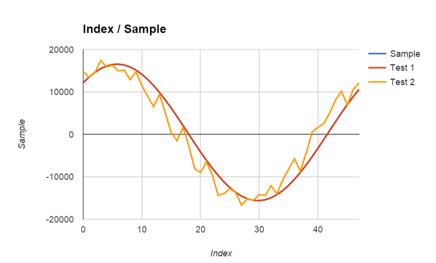
I'm not doing ping pong but I'm also not doing any processing. If I service the McASP buffers directly in a for loop I get the red line but if I try to configure the EDMA the results looks like the orange line.


I have verified everything that I can, gone through forums and read through the documentation but I can't figure out how to do this with EDMA.

Any suggestions will be greatly appreciated.

Here is my code:

unsigned short dataout[48] = {
0x0000, 0x10b4, 0x2120, 0x30fb, 0x3fff, 0x4dea, 0x5a81, 0x658b,
0x6ed8, 0x763f, 0x7ba1, 0x7ee5, 0x7ffd, 0x7ee5, 0x7ba1, 0x763f,
0x6ed8, 0x658b, 0x5a81, 0x4dea, 0x3fff, 0x30fb, 0x2120, 0x10b4,
0x0000, 0xef4c, 0xdee0, 0xcf06, 0xc002, 0xb216, 0xa57f, 0x9a75,
0x9128, 0x89c1, 0x845f, 0x811b, 0x8002, 0x811b, 0x845f, 0x89c1,
0x9128, 0x9a76, 0xa57f, 0xb216, 0xc002, 0xcf06, 0xdee0, 0xef4c
};

unsigned int datain[48];

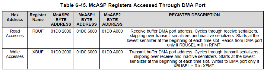
void *mcasp_xmt_register = (void *)(MCASP1_BASE + 0x214);
void *mcasp_rcv_register = (void *)(MCASP1_BASE + 0x280);

/*
* ======== main ========
*/
void main()
{
/* Initialize i2c */
I2C_Init();

// Configure DS1 (User LEDs) as output
GPIO_Set_Direction(12, GPIO_OUT);

// Turn off LEDs (Desired initial state)
GPIO_Set_Output(12, GPIO_ON);

BIOS_start();
}

/*
* ======== Task Function 0 ========
*/
void task0function()
{

short msec;
short sec;
short sample;

for ( sample = 0 ; sample < 48 ; sample++ )
{
datain[sample]=0;
// dataout[sample]=dataout[sample]<<16;
}

/*Initialize edma*/
Edma3_Init();

Edma3_Setup_McASP_XMT(dataout, mcasp_xmt_register, 2, 48);

// Edma3_Ping_XMT(dataout, dataout, mcasp_xmt_register, 2, 48);

Edma3_Enable_Channel(EDMA_MCASPTXCH, 0);

Edma3_Enable_Interrupt(EDMA_MCASPTXCH_TCC);

//Intrinsic Function to Enable Interrupts
_enable_interrupts();

/* Initialize AIC3106 */
AIC3106_Initialize();

/* Initialize McASP1 */
MCASP_Open(MCASP_1);

/* Record Tone */

for ( sec = 0 ; sec <2 ; sec++ )
{
for ( msec = 0 ; msec < 1000 ; msec++ )
{
for ( sample = 0 ; sample < 48 ; sample++ )
{
/* Send a sample to the left channel */
// while ( ! ( MCASP1_SRCTL5 & 0x10 ) );
// MCASP1_XBUF5_32BIT = (dataout[sample] << 0);
/* Read the right sample */
while ( ! ( MCASP1_SRCTL0 & 0x20 ) );
datain[sample] = MCASP1_RBUF0_32BIT >> 0;
/* Send a sample to the right channel */
// while ( ! ( MCASP1_SRCTL5 & 0x10 ) );
// MCASP1_XBUF5_32BIT = (dataout[sample] << 0);
/* Read the left sample */
while ( ! ( MCASP1_SRCTL0 & 0x20 ) );
datain[sample] = MCASP1_RBUF0_32BIT >> 0;
}
}
}

//Intrinsic Function to Disable Interrupts
_disable_interrupts();

/* Close Codec */
AIC3106_Close();

/* Close McASP */
MCASP_Close(MCASP_1);

/* Close I2C */
I2C_Close( );

for ( sample = 0 ; sample < 48 ; sample++ )
{
datain[sample]=datain[sample] >> 16;
System_printf("%d\n",(short)datain[sample]);
}

BIOS_exit(0);
}


/*

* ======== clk0Fxn =======
*/
void clk0function(UArg arg0)
{
GPIO_Toggle(12);
}

/*
* ======== edma3isr ========
*/

int edma3ccisr()
{
while(edma3ccRegs->IPR != 0)
{
if (edma3ccRegs->IPR & (1 << EDMA_MCASPTXCH_TCC))
{
Edma3_Clear_Interrupt(EDMA_MCASPTXCH_TCC);
// Semaphore_post(xmtsemhandle);
}
if (edma3ccRegs->IPR & (1 << EDMA_MCASPRXCH_TCC))
{
Edma3_Clear_Interrupt(EDMA_MCASPRXCH_TCC);
// Semaphore_post(rcvsemhandle);
}
}
return 0;
}

and here is my EDMA setup:

int Edma3_Setup_McASP_XMT(void *src, void *dst, unsigned int sample_size, unsigned int sample_count)
{
CSL_Edma3ccParamSetRegs param;

param.SRC = (unsigned int)src;
param.DST = (unsigned int)dst;
param.A_B_CNT = (2 << 16) | (sample_size); // actual format: BCNT|ACNT ACnt is 2 bytes or 16 bit word
param.CCNT = sample_count; // our array has 48 samples for single 48 KHz period
param.SRC_DST_BIDX = (0 << 16) | 0; // actual format: DSTBIDX|SCRBIDX
param.SRC_DST_CIDX = (0 << 16) | sample_size; // actual format: DSTCIDX|SRCCIDX
param.OPT = (1 << 20) | (EDMA_MCASPTXCH_TCC << 12); // transfer complete interrupt enabled, A Synch Mode
param.LINK_BCNTRLD = (2 << 16) | (EDMA_MCASPTXCH_RLD << 5); // actual format: BCNTRLD|LINK
Edma3_Write_PaRAM(EDMA_MCASPTXCH, &param);
Edma3_Write_PaRAM(EDMA_MCASPTXCH_RLD, &param);

return 0;
}

  • Hoffiz,

    Your red line sine wave is much more smooth than I would expect from a sampled waveform. In the orange line drawing, you can see the 10 individual sample points between vertical lines, and there should be that same step size on the red line. So I am wondering exactly what that line represents.

    I do not see the code that sends data directly to the McASP to generate the red line. This would be vital for comparing how your EDMA3 setup is working compared with that code. Please post a copy of that part of the code or point me to where I am missing it in your original post, above. If it is the code that is commented out, that tells me it was not running, so it is hard to figure out a comparison; if that is all I am missing, please let me know.

    For a test, please try changing the EDMA3 destination address to a memory buffer area and also change the SRCBIDX to 2 so the pointer will increment. Just store it all in a single linear buffer, even if you have to change the LINK field to 0xFFFF so it stops after one sine wave. Please post the samples from that buffer, which will confirm what actual data is being sent out to the McASP XBUF5 port.

    When using the DMA transfer method, accesses should be made using the XRBUF locations with XBUSEL=0 in XFMT. Below from the C6747 datasheet (same as L137 in these respects), respectively.

    I am not sure how this would affect the data as shown, but using the XBUF address is the correct way to use the EDMA3 for writing to a McASP.

    We will continue looking at this after you can capture those output samples being sent to XBUF and also to the RAM buffer. And I will try to follow your commented code with your help.

    Regards,
    RandyP

  • Hi Randy,

    Thank you very much. I have actually implemented the same suggestion before the your reply. Although it got rid of the saw-tooth response I'm experiencing a different issue. The red and orange lines are simply plotting the printf from the destination in Google Docs.

    This is my setup, I'm generating

    unsigned short dataout[48] to XBUF 5 connecting a cable from line out to line int and reading RBUF0.

    I changed the code to write to the DMA port by changing the src and dst of the respective DMA setups and setting RBUSEL and XBUSEL appropriately. 

    void *mcasp_xmt_dmaport = (void *)(MCASP1_DATA);
    void *mcasp_rcv_dmaport = (void *)(MCASP1_DATA);

    here are the functions I'm playing with:

    // setup_edma_pingpong_xmt(xmt_ping_L, xmt_pong_L, xmt_ping_R, xmt_pong_R, mcasp_xmt_dmaport, BYTES, SAMPLES);

    // setup_edma_ping_xmt(xmt_ping_L, xmt_ping_R, mcasp_xmt_dmaport, BYTES, SAMPLES);

    Edma3_Setup_McASP_XMT(xmt_ping_L, mcasp_xmt_dmaport, BYTES, SAMPLES);

    // setup_edma_pingpong_rcv(mcasp_rcv_dmaport, rcv_ping_L, rcv_pong_L, rcv_ping_R, rcv_pong_R, BYTES, SAMPLES);

    // setup_edma_ping_rcv(mcasp_rcv_dmaport, rcv_ping_L, rcv_ping_R, BYTES, SAMPLES);

    Edma3_Setup_McASP_RCV(mcasp_rcv_dmaport, rcv_ping_L, BYTES, SAMPLES);

    Edma3_Enable_Interrupt(EDMA_XMT_PING_TCC);
    // Edma3_Enable_Interrupt(EDMA_XMT_PONG_TCC);
    Edma3_Enable_Interrupt(EDMA_RCV_PING_TCC);
    // Edma3_Enable_Interrupt(EDMA_RCV_PONG_TCC);

    there is 2 sets one for xmt and one for rcv. Each set has PingPont to Left and Right, a Ping to Left and Right and Ping to Left. The Ping Pong Left and Right works great but the other two have kind of like a lag or delay. In the following picture Ping R is expected to be zero.

    here is the code setting up the Edma Requests:

    void Edma3_Setup_McASP_XMT(void *src, void *dst, unsigned int bytes, unsigned int samples)
    {
    CSL_Edma3ccParamSetRegs param;

    param.OPT = (EDMA_XMT_PING_TCC << 12) | (1 << 20); // transfer complete interrupt enabled, A Synch Mode
    param.SRC = (unsigned int)src;
    param.A_B_CNT = (2 << 16) | bytes; // actual format: BCNT|ACNT ACnt is 2 bytes or 16 bit word
    param.DST = (unsigned int)dst;
    param.SRC_DST_BIDX = (0 << 16) | 0; // actual format: DSTBIDX|SCRBIDX
    param.LINK_BCNTRLD = (2 << 16) | (EDMA_XMTPING * 0x20); // actual format: BCNTRLD|LINK
    param.SRC_DST_CIDX = (0 << 16) | (bytes); // actual format: DSTCIDX|SRCCIDX
    param.CCNT = samples; // our array has 48 samples for single 48 KHz period
    Edma3_Write_PaRAM(EDMA_MCASPTXCH, &param);

    // 2. setup ping PaRAM set (to be reloaded later)
    Edma3_Write_PaRAM(EDMA_XMTPING, &param);
    }

    and here is the McASP configuration:

    short MCASP_Open()
    {
    mcasp = &MCASP_MODULE_1;

    /* ---------------------------------------------------------------- *
    * McASP1 is in MASTER mode. *
    * BCLK & WCLK come from McASP1 *
    * DIN is used by write16/write32 *
    * DOUT is usec by read16/read32 *
    * www.ti.com/.../spru041j.pdf pg 36 *
    * ---------------------------------------------------------------- */
    mcasp->regs->GBLCTL = 0; // Reset
    mcasp->regs->RGBLCTL = 0; // Reset RX
    mcasp->regs->XGBLCTL = 0; // Reset TX
    mcasp->regs->PWRDEMU = 1; // Free-running

    /* RX */
    mcasp->regs->RMASK = 0xffffffff; // No padding used
    mcasp->regs->RFMT = 0x00018070; // MSB 16bit, 1-delay, no pad, CFGBus, changed to DMA Port
    mcasp->regs->AFSRCTL = 0x00000112; // 2TDM, 1bit Rising, INTERNAL FS, word
    mcasp->regs->ACLKRCTL = 0x000000AF; // Rising INTERNAL CLK(from tx side)
    mcasp->regs->AHCLKRCTL = 0x00000000; // INT CLK (from tx side)
    mcasp->regs->RTDM = 0x00000003; // Slots 0,1
    mcasp->regs->RINTCTL = 0x00000000; // Not used
    mcasp->regs->RCLKCHK = 0x00FF0008; // 255-MAX 0-MIN, div-by-256

    /* TX */
    mcasp->regs->XMASK = 0xffffffff; // No padding used
    mcasp->regs->XFMT = 0x00018070; // MSB 16bit, 1-delay, no pad, CFGBus
    mcasp->regs->AFSXCTL = 0x00000112; // 2TDM, 1bit Rising edge INTERNAL FS, word
    mcasp->regs->ACLKXCTL = 0x000000AF; // ASYNC, Rising INTERNAL CLK, div-by-16
    mcasp->regs->AHCLKXCTL = 0x00000000; // INT CLK, div-by-4
    mcasp->regs->XTDM = 0x00000003; // Slots 0,1
    mcasp->regs->XINTCTL = 0x00000000; // Not used
    mcasp->regs->XCLKCHK = 0x00FF0008; // 255-MAX 0-MIN, div-by-256

    mcasp->regs->SRCTL5 = 0x000D; // MCASP1.AXR1[5] --> DIN
    mcasp->regs->SRCTL0 = 0x000E; // MCASP1.AXR1[0] <-- DOUT
    mcasp->regs->PFUNC = 0; // All MCASPs
    mcasp->regs->PDIR = 0x14000020; // All inputs except AXR0[5], ACLKX1, AFSX1

    mcasp->regs->DITCTL = 0x00000000; // Not used
    mcasp->regs->DLBCTL = 0x00000000; // Not used
    mcasp->regs->AMUTE = 0x00000000; // Not used

    /* Starting sections of the McASP*/
    mcasp->regs->XGBLCTL |= GBLCTL_XHCLKRST_ON; // HS Clk
    while ( ( mcasp->regs->XGBLCTL & GBLCTL_XHCLKRST_ON ) != GBLCTL_XHCLKRST_ON );
    mcasp->regs->RGBLCTL |= GBLCTL_RHCLKRST_ON; // HS Clk
    while ( ( mcasp->regs->RGBLCTL & GBLCTL_RHCLKRST_ON ) != GBLCTL_RHCLKRST_ON );

    mcasp->regs->XGBLCTL |= GBLCTL_XCLKRST_ON; // Clk
    while ( ( mcasp->regs->XGBLCTL & GBLCTL_XCLKRST_ON ) != GBLCTL_XCLKRST_ON );
    mcasp->regs->RGBLCTL |= GBLCTL_RCLKRST_ON; // Clk
    while ( ( mcasp->regs->RGBLCTL & GBLCTL_RCLKRST_ON ) != GBLCTL_RCLKRST_ON );

    mcasp->regs->XSTAT = 0x0000ffff; // Clear all
    mcasp->regs->RSTAT = 0x0000ffff; // Clear all

    mcasp->regs->XGBLCTL |= GBLCTL_XSRCLR_ON; // Serialize
    while ( ( mcasp->regs->XGBLCTL & GBLCTL_XSRCLR_ON ) != GBLCTL_XSRCLR_ON );
    mcasp->regs->RGBLCTL |= GBLCTL_RSRCLR_ON; // Serialize
    while ( ( mcasp->regs->RGBLCTL & GBLCTL_RSRCLR_ON ) != GBLCTL_RSRCLR_ON );

    /* Write a 0, so that no underrun occurs after releasing the state machine */
    mcasp->regs->XBUF5 = 0;
    mcasp->regs->RBUF0 = 0;

    mcasp->regs->XGBLCTL |= GBLCTL_XSMRST_ON; // State Machine
    while ( ( mcasp->regs->XGBLCTL & GBLCTL_XSMRST_ON ) != GBLCTL_XSMRST_ON );
    mcasp->regs->RGBLCTL |= GBLCTL_RSMRST_ON; // State Machine
    while ( ( mcasp->regs->RGBLCTL & GBLCTL_RSMRST_ON ) != GBLCTL_RSMRST_ON );

    mcasp->regs->XGBLCTL |= GBLCTL_XFRST_ON; // Frame Sync
    while ( ( mcasp->regs->XGBLCTL & GBLCTL_XFRST_ON ) != GBLCTL_XFRST_ON );
    mcasp->regs->RGBLCTL |= GBLCTL_RFRST_ON; // Frame Sync
    while ( ( mcasp->regs->RGBLCTL & GBLCTL_RFRST_ON ) != GBLCTL_RFRST_ON );

    return 0;
    }

  • Hoffiz,

    The description of the ping and pong and left and right buffers is very confusing to me. Since you have solved the original problem, and thank you for describing that solution here, please mark you post above with Verify Answer and then start a new thread with the new question. Please re-phrase the ping/pong/etc. descriptions for us (me).

    I know the EDMA3 well enough to look at the few registers and fields and understand what is happening, at least enough to ask you questions about it. But I am not good enough to mentally cover 75 lines of McASP setup. Since I have started working with you here, it will be easier to get McASP help in the new thread which I will stay off of unless it really is about the EDMA3 operation.

    I will address your EDMA3 issues on the other thread, which hopefully is still a concern.

    Regards,

    RandyP

  • Hi Randy,

    I completely understand. I do think your suggestion was helpful and I'm dealing with some settling or race condition issue. I can see and hear the tone I'm expecting but when capturing the first few samples are 0, as you can see in the pictures, then there is a little of an overshoot, then you can see a nice smooth 1 KHz tone.

    I will wait for the other thread, like you mention I also think I have a McASP configuration issue. The EDMAs are actually correctly configured since by moving some lines around (yes that is the strange part) I can get the expected result. The function is right, I think the issue is with my order of configuration.

    Thank you for your help.
  • Hoffiz,

    It is possible that the AIC codec chip on the board for thee DAC uses a multi-tap filter between the input samples and the output analog value. This would easily explain the strange startup behavior you are seeing. Some boards also have a simple RC filter on the outputs that could cause odd startup behavior.

    If the startup waveform continues to be an irritant, you may want to lookup the AIC datasheet and check how it gets configured - there may be a way to adjust the internal filter, but my recollection is that some of them cannot be completely disabled. I am not positive about this, but wanted to offer it as a possible clue; hopefully it is not a misleading clue.

    Regards,
    RandyP
  • Hi Randy,

    I don't think that will be the case. In my EDMA setup, for the Ping Pong left and right, Ping Left and Right and Ping Left only, I have the same AIC 3106 configuration. Having a scope will be great but sadly I'm relying on the AIC3106 input. I solved the issue but I can't pin point to a specific change. I will have to do some more digging before I can share what was the solution. Something that I do recall helping is the McASP configuration for I2S was wrong. The spectrum digital example had 0 delay and was shifting down by 15. This is wrong, the correct set for I2S per the McASP documentation is to delay by 1 allowing me to shift the 32 bit down by 16 as expected.