This thread has been locked.

If you have a related question, please click the "Ask a related question" button in the top right corner. The newly created question will be automatically linked to this question.

C667x CPSW - level 2 switch functionality configuration

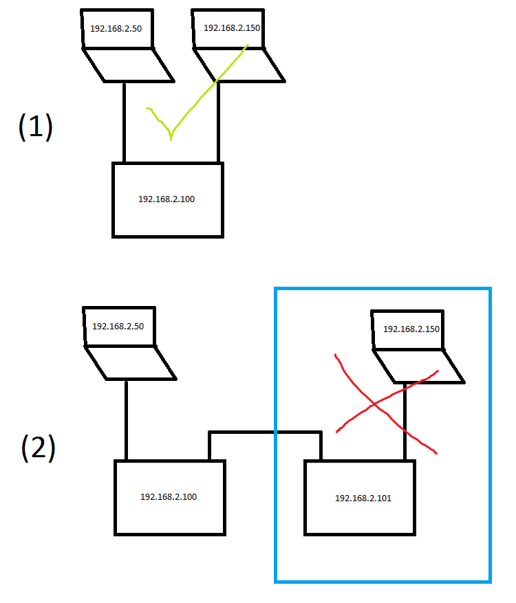
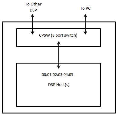
We have developed a custom PCB based on the C6672 DSP that has both Ethernet SGMII channels fed into a PHY. To be able to communicate with multiple boards through Ethernet, we would like to use the following setup:

This means that each DSP board has one IP address assigned that is used to communicate with the PC application. Both Ethernet SGMII ports are used to allow Ethernet traffic to be forwarded to the next DSP boards, which is basic level 2 switching functionality as far as I can see.

So far, however, we haven't been able to figure out how to configure the CPSW to act as a (simple) L2 switch. We did manage to modify 'nimu_eth.c' from the transport library in such a way that the IP address of the board can be reached through both SGMII Ethernet channels, but we're kind of stuck from that point.

Anyone who can help us get the L2 switching functionality of the CPSW to work? Any help is greatly appreciated!

PS: our modified version of nimu_eth.c is attached to this post.8562.nimu_eth.c

  • Hi,
    Are you using different PHY and EMAC port than EVM board ?
    If you are using different EMAC port than EVM, say EMAC0, then refer to the following TI wiki page.

    You may need to change the PHY and platform code.

    C:\ti\pdk_C6678_1_1_2_6\packages\ti\platform\evmc6678l\platform_lib\src\
    evmc6678_phy.c
    platform.c

    processors.wiki.ti.com/.../NDK,_PA_Resource_Wiki_for_Keystone_Devices

    You can use the following PA example projects to send packets to other board.

    C:\ti\pdk_C6678_1_1_2_6\packages\ti\drv\exampleProjects\PA_emacExample_exampleProject
    C:\ti\pdk_C6678_1_1_2_6\packages\ti\drv\exampleProjects\PA_multicoreExample_exampleProject
    C:\ti\pdk_C6678_1_1_2_6\packages\ti\drv\exampleProjects\PA_simpleExample_exampleProject
  • Hi,

    we've already successfully modified the platform library etc in such a way that both PHY's are initialised properly and can be communicated through. Additionally, we've modified nimu_eth.c according to the following TI E2E post:

    We are now using the helloWorld example application to test our Ethernet setup and right now when the Ethernet cable is connected to EITHER PHY 0 or 1, we get a successfull reply from the DSP. So traffic from either PHY is flowing succesfully into port 0 of the CPSW. Exactly what we want!

    However, we would also like to use the CPSW to route traffic coming from PHY 0 that is not meant for CPSW port 0 back to the PHY 1 (and vica versa) so that the CPSW acts like a 'normal' level 2 switch. Can you help us achieve that?

  • I have had some progress, but not entirely there. To explain what works and what doesn't , see the graphic below. '2.50' and '2.150' are PC's/laptops and '2.100' and '2.101' are our custom PCB's.

    Scenario 1 in the picture: using the CPSW of the DSP I am now able to communicate between two PC's that are both connected to one of the PHY ports of our custom PCB. Additionally, both PC's can reach CPSW Port 0 (aka the NDK program running on the DSP) as well. Great!

    Scenario 2 in the picture: as soon as I add another CPSW switch to the chain, I cannot reach the PC on the other end of the chain. The same goes for the 2nd DSP in the chain (as seen from the PC), it cannot be reached either. So for instance, laptop '2.50' cannot reach DSP board '2.101' or laptop '2.150' (the blue section).

    The current implementation is based on nimu_eth.c from this thread:

    I've modified that file according to this post (implemented only the starred items!): 

    1462.nimu_eth.c

    I've attached the resulting nimu_eth.c to this post.

    From inspecting Wireshark captures, it looks like ARP requests aren't properly broadcasted from the 'blue section' in the graphic to laptop '2.50' and I suspect that is the problem, but I cannot figure our yet how to configure the CPSW to switch that traffic properly. Does anyone how to do this?

    Many thanks in advance,

    Oane

  • Anybody knows what could be the problem?

  • Sorry for the delay...I am escalating this one....

  • Oane,

    Line 1659 in the attached 8562.nimu_eth.c file configures the CPSW to operate in ALE bypass mode. This means that all packets received at the external Ethernet ports will bypass the ALE (and the L2 switching functionality) and go directly to host port 0. 

    If you would like the CPSW to perform L2 switching (based on MAC addresses) then you will need to disable ALE bypass. You will also need to add an entry to your ALE table for the MAC address that you would like your 6672 device to allow into host port 0. 

    See section 2.3.6.5 in the GbE User's Guide for an explanation of the ALE forwarding process (http://www.ti.com/lit/ug/sprugv9d/sprugv9d.pdf). 

    Jason Reeder

  • Hi Jason,

    thanks for the help so far. However, I had already posted an update to my original post where there's a new version of nimu_eth.c (1462.nimu_eth.c) in which the ALE bypass function was disabled: 

    But as I am describing there, passing Ethernet data from a PC through 2 daisy chained DSP's still doesn't work, nor can I can communicate between a PC and the 2nd DSP in the chain. I am right in assuming that this should be possible with the CPSW functionality, theoretically speaking?

    My latest tests show that no gratuitous ARP requests are received during a scenario where a PC is hooked up to DSP1 and they are communicating. If I then powerup DSP2 in the chain, no gratuitous ARP is observed by the PC and therefore the PC is unaware of the existence of DSP2 in the chain. This in turn does not allow me to ping DSP2 nor communicate with it. That's what my problem is, and that's what I would like to fix. Can you help me with this?

    Best regards,

    Oane 

  • Oane,

    Yes, what you are describing should be possible with the CPSW. Here are some things to know:

    • The CPSW only operates on MAC addresses, IP addresses are only used once a packets has made it further into the DSP device through host port 0 of the CPSW
    • The 'ALE Learning Process' (section 2.3.6.6 of the GbE User's Guide) is based on a packet's SourceMAC address
      • If an address is learned (based on the if-else rules of the learning process) then an ALE entry is created that ties that Source MAC address to the port that the packet entered the CPSW through
      • In your Scenario 2 above, when the computer  with the IP address 192.168.2.150 sends a packet into the right-most DSP, then an ALE entry should be learned that ties the MAC address of that computer to that DSPs right-most port.
    • The 'ALE VLAN Unaware Lookup Process' (section 2.3.6.5.3) is based on a packet's DestinationMAC address.
      • This lookup process is how the switch determines which ports to forward the packet to (or if it should discard the packet)
      • In your case (VLAN unaware), your REG_MCAST_FLOOD_MASK will be '111' (all ports), your UNREG_MCAST_FLOOD_MASK will be '111' (all ports), and your VLAN_MEMBER_LIST will be '111' (all ports). So, anywhere you see those three variables used throughout the 'ALE VLAN Unaware Lookup Process' then you should assume that the mask is all ports.
    • The CPSW is a 3-port switch with one host port (port 0) and two external Ethernet ports (port 1 and port 2)

    My understanding of the Learning Process and the Lookup Process is that during initialization you should only need to manually add ALE table entries for Destination MAC addresses that you would like to be allowed into the DSP cores through host port 0.

    The Learning Process should take care of adding the ALE table entries for other devices that are connected on external Ethernet ports (as long as learning is enabled, which from your code I think it is). 

    Packets entering the CPSW through external Ethernet ports that do not match any ALE table entry should be forwarded out of the other external Ethernet port based on the Lookup Process (2.3.6.5.3 box 3 - Unicast packet where destination address is not found). 

    You should be able to use the descriptions from the GbE User's Guide of the Learning Process and the Lookup Process, along with Wireshark and a dump of your ALE table, and understand where each packet is being forwarded or dropped.

    Let me know if this doesn't make sense,

    Jason Reeder

  • Hi Jason,

    thanks for your extensive answer (and confirming that our scenario is a valid one).

    To allow for better debugging of what is going on, I've expanded a CPSW debugging GEL file I found here on the forum somewhere with a function to dump the contents of the ALE table (GEL file attached to this post).

    cpsw_stats_print.gel


    When DSP1 is booted up and it's connected to the PC (no other connections yet), the contents of the ALE table on DSP1 are as follows:

    C66xx_0: GEL Output: -----------------------------------------------
    C66xx_0: GEL Output: ALE table contents.
    C66xx_0: GEL Output: -----------------------------------------------
    C66xx_0: GEL Output: ALE[16] raw: [2]-0x00000004 [1]-0xD00000E0 [0]-0x4C1F2EB7, port: 1, entry type: 1, mcast/ucast: 3
    C66xx_0: GEL Output: ALE[32] raw: [2]-0x00000000 [1]-0xD000B499 [0]-0x4C0576B9, port: 0, entry type: 1, mcast/ucast: 3
    C66xx_0: GEL Output: -----------------------------------------------

    This is exactly what I would expect. There are 2 entries, our own MAC address (ALE entry #32) and the PC's MAC address (ALE entry #16). DSP1 can be pinged from PC1 etc, all good.

    Scenario 1:

    When connecting PC2 to the 2nd port of DSP1, the contents of the ALE table on DSP1 is as follows:

    C66xx_0: GEL Output: -----------------------------------------------
    C66xx_0: GEL Output: ALE table contents.
    C66xx_0: GEL Output: -----------------------------------------------
    C66xx_0: GEL Output: ALE[16] raw: [2]-0x00000004 [1]-0xD00000E0 [0]-0x4C1F2EB7, port: 1, entry type: 1, mcast/ucast: 3
    C66xx_0: GEL Output: ALE[17] raw: [2]-0x00000008 [1]-0xD0000015 [0]-0xC5B8EC4C, port: 2, entry type: 1, mcast/ucast: 3
    C66xx_0: GEL Output: ALE[32] raw: [2]-0x00000000 [1]-0xD000B499 [0]-0x4C0576B9, port: 0, entry type: 1, mcast/ucast: 3

    Observations:

    • As can be seen, ALE entry #17 is added, which contains the MAC address of PC2. Exactly what I would expect.
    • As soon as PC2 is connected, Wireshark on PC1 is observing gratuitous ARP requests from PC2 (expected)
    • DSP1 and PC2 can be pinged / connected to, all fine.


    Scenario 2:

    Now, instead of connecting PC2 to the 2nd port of DSP1, we connect DSP2 to the 2nd port of DSP1. After a fresh boot of PC1 and DSP1 and then connecting DSP2 we get the following ALE table on DSP1:

    C66xx_0: GEL Output: -----------------------------------------------
    C66xx_0: GEL Output: ALE table contents.
    C66xx_0: GEL Output: -----------------------------------------------
    C66xx_0: GEL Output: ALE[16] raw: [2]-0x00000004 [1]-0xD00000E0 [0]-0x4C1F2EB7, port: 1, entry type: 1, mcast/ucast: 3
    C66xx_0: GEL Output: ALE[32] raw: [2]-0x00000000 [1]-0xD000B499 [0]-0x4C0576B9, port: 0, entry type: 1, mcast/ucast: 3
    C66xx_0: GEL Output: -----------------------------------------------

    Observations:

    • No ALE entry for DSP2 in the ALE table
    • No gratuitous ARP requests are observed in Wireshark on PC1 for DSP2
    • DSP1 can be pinged, DSP2 cannot be pinged


    In conclusion:

    It seems that the gratuitous ARP request from DSP2 does not lead to an ALE entry being added, while the gratuitous ARP request from PC2 does. This means there is a difference between the ARP request packet from PC2 and the one from DSP2, but what could cause that difference and how can it be solved?

    PS: one more bit of information, just in case... the contents of the ALE registers for DSP1:

    C66xx_0: GEL Output: -----------------------------------------------
    C66xx_0: GEL Output: ALE Registers
    C66xx_0: GEL Output: -----------------------------------------------
    C66xx_0: GEL Output: CPSW ALE CONTROL ................ 0x80000000
    C66xx_0: GEL Output: CPSW ALE PORT0 CONTROL ................ 0x00000003
    C66xx_0: GEL Output: CPSW ALE PORT1 CONTROL ................ 0x00000003
    C66xx_0: GEL Output: CPSW ALE PORT2 CONTROL ................ 0x00000003
    C66xx_0: GEL Output: -----------------------------------------------

  • Jason,

    thanks for jumping here.

  • Small update:
    it looks like the switch *is* configured correctly at this point in time, but something seems off with building up a link between two DSP's. I will update this post when I found the root of the problem.
  • Oane,

    Thanks for the update. Let us know what you find.

    Jason Reeder

  • Hi Jason,

    as it turns out, the two DSP's whom are both configured fixed to 100 Mbit/FD, are not getting a link. Setting both DSP's to Auto Negotiation does work and they both link up at 100 Mbit / FD through auto negotiation anyways... very weird. Especially since a DSP connected to a PC (in auto negotiation mode OR fixed at 100 Mbit/FD) always managed to get a link. Therefore, I did not expect this to be the problem.

    I found out what the problem was though by first looking at the ALE table (as you suggested) and send the same gratuitous ARP packet that DSP2 would normally send by using Colasoft Packetbuilder running on a PC. When that ARP request was received by DSP1, the correct entry was added to the ALE. So then I looked at the actual link and decided to add a normal, consumer grade L2 switch between the two DSPs; lo and behold, the same gratuitous ARP request from DSP2 was observed by DSP1 and the ALE entry was added accordingly. So then I knew it had to be the link between the DSPs...

    So in the end my updated post had already the correct settings for the CPSW, but there was another issue that prevented our intended scenario. Your post did help a lot though for confirming that we were on the right track and explained the CPSW functionality crystal clear. Many thanks for that.

    Best regards,

    Oane Kingma

  • Oane,

    Good to hear. Thanks for coming back and updating the thread.

    Jason Reeder