This thread has been locked.

If you have a related question, please click the "Ask a related question" button in the top right corner. The newly created question will be automatically linked to this question.

Abnormal wave shape with AM3354

Other Parts Discussed in Thread: AM3354

When I test my AM3354 designed board,I found some Abnormal wave shape ,such as:

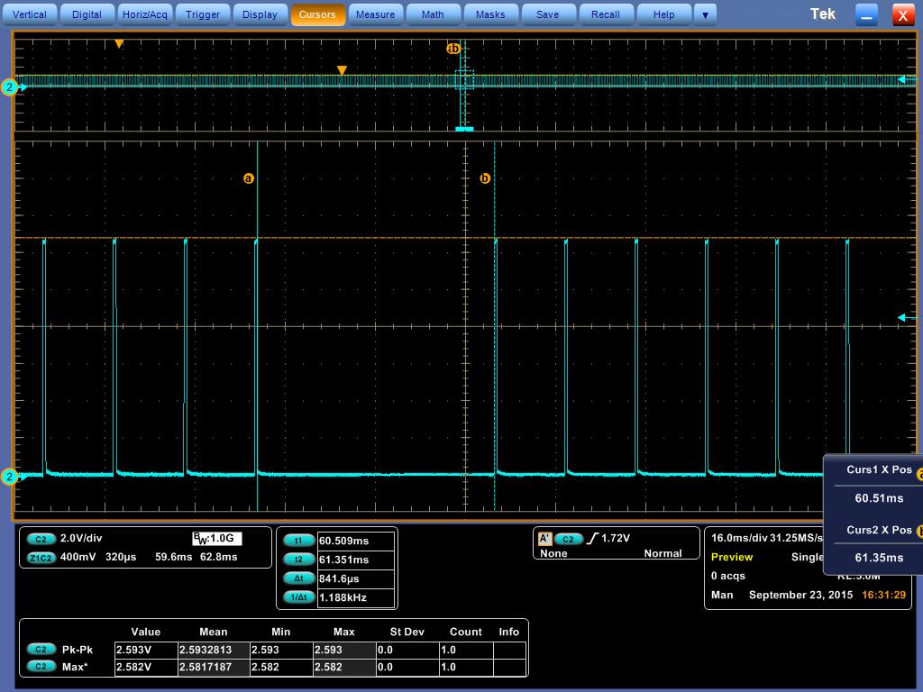
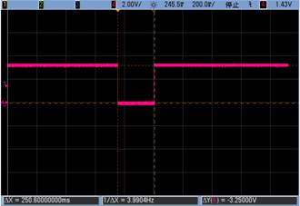
1.test  buzzer wave(packge pin A13) IO for PWM0A,buzzer a corresponding waveform in time, 20 ms arose among high level and 530 ms low level driver level:

2.AM3354 chip to reset button is there any time requirement?(for pin A10 ,WARMRSTn)
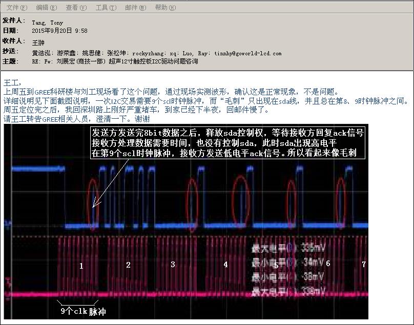
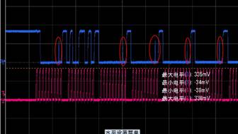
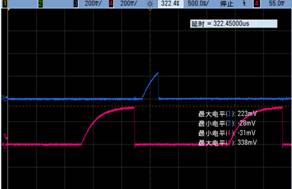
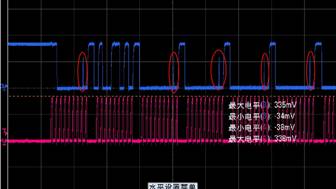
3.I2C2 (connect to CTP)communications SDA waveform expansion plan is as follows, burr peak of 280 ns.
Looking forward to your reply,thank you~

  • Hi,

    The pictures you have attached are barely visible. Could you post them in higher resolution? On your questions:

    1. What software are you using? If this is the Linux SDK PWM driver it will not work on this pin.

    2. Can you please clarify? Input or output time requirement?

    3. What is the value of the pullup resistors on the I2C lines?

  • Hi,RE as follow:

    1、The eHRPWM driver is from  kernel_gr335x.tar by TI in 2010.The pwm frequence is 4KHz.The buzzer's wave may not normally. It's has 20 us arose among high level and 530 us low level driver level.The wave as follow:

    2、I need the output time for chip reset at pin A10(zcz);

    3、The pullup resistors on the I2C lines are 4.7Kohm,1/16W,5%,0402,SMD.

    Thank you your reply~

  • elenin said:
    1、The eHRPWM driver is from  kernel_gr335x.tar by TI in 2010.The pwm frequence is 4KHz.The buzzer's wave may not normally. It's has 20 us arose among high level and 530 us low level driver level.The wave as follow:

    I don't see any picture attached. However "The eHRPWM driver is from  kernel_gr335x.tar by TI in 2010" - this is obsolete from a long time. Please use the latest SDK version: http://software-dl.ti.com/sitara_linux/esd/processor-sdk/PROCESSOR-SDK-LINUX-AM335X/latest/index_FDS.html

    elenin said:
    2、I need the output time for chip reset at pin A10(zcz);

    See section 8.1.7.4.1.2 from the AM335X TRM Rev. L. Figures 8-21 and 8-22 show the timings.

    elenin said:
    3、The pullup resistors on the I2C lines are 4.7Kohm,1/16W,5%,0402,SMD.

    Try reducing these to 1.5kOhm if you have I2C issues.

  • HI,RE as follow:

    1、The pwm wave as follow:

    Buzzer works well, but the wave  is unusual, Would  you explain to the following two points exception?

    (1)A response of the buzzer waveform abnormal 550 us or 841 us the low level of drive level (random).

    (2)Of every response waveform in the final buzzer will have a continuous high level of 250 us.

    2、How much is the chip reset time? Figures 8-21 and 8-22 does not give the exact time.Would you show me the exact time ?

    3、I2C2 communication is normal, buthow to eliminate the waveform of the burr ?Why do you use the 1.5 k replace  4.7 k?

    Thank you for your reply~

  • elenin said:
    Buzzer works well, but the wave  is unusual, Would  you explain to the following two points exception?

    (1)A response of the buzzer waveform abnormal 550 us or 841 us the low level of drive level (random).

    (2)Of every response waveform in the final buzzer will have a continuous high level of 250 us.

    I have already posted that the driver you use is very old and no longer supported.

    elenin said:
    2、How much is the chip reset time? Figures 8-21 and 8-22 does not give the exact time.Would you show me the exact time ?

    You can calculate it yourself from the document section I gave you. I don't know your crystal frequency.

    elenin said:
    3、I2C2 communication is normal, buthow to eliminate the waveform of the burr ?Why do you use the 1.5 k replace  4.7 k?

    These spikes are the ACK signal from the Slave device. They are quite normal, because the data line switches direction in this moment. 1.5K is the value used in TI reference designs, but there is no need to change from 4.7K if your I2C works fine.