This thread has been locked.

If you have a related question, please click the "Ask a related question" button in the top right corner. The newly created question will be automatically linked to this question.

OMAPL137 UART example rCSL

Other Parts Discussed in Thread: OMAPL138

I have been trying to figure out the solution to an issue for sometime with no luck. I had working examples for UART2 both the hyper-terminal and loopback from: "quickStartOMAPL1x_rCSL". Yesterday I started trying to migrate/port the starter-ware uartecho for the omapl138 to the omapl137. After a very manual adding files and reviewing the necessary definitions against the CSL macro of the "quickStartOMAPL1x_rCSL" I was able to build successfully.  When I went to try the uart2echo example it did not work. As expected it was the first attempt. Trying to troubleshoot and make sure everything is working I went back to the working rCSL examples. For some reason I can't get them to work anymore. I have a FTDI USB to serial that I know worked with the hyper-terminal example and I also now the loopback example worked. 

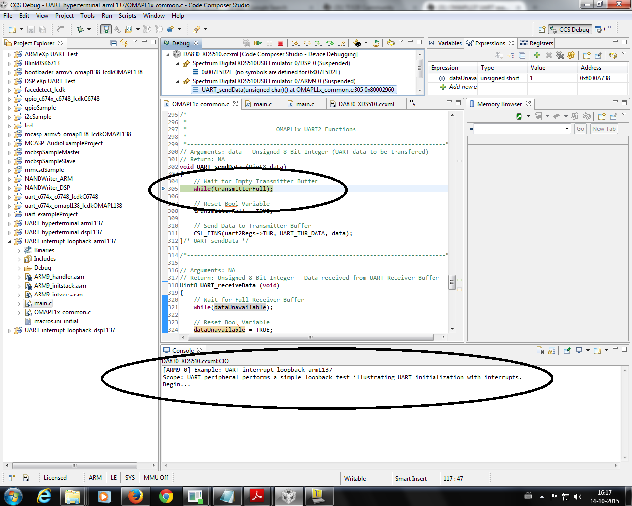
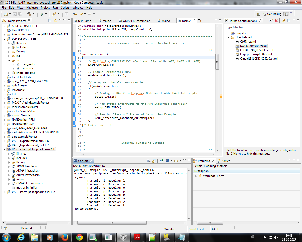
As I recall the loopback example does not even need a cable since it configures the UART into loopback mode.

At this point I'm out of ideas, is there anything you could suggest for me to try?

  • Hi Hoffiz,
    Did you check the PINMUX8_31_28 and PINMUX9_3_0 register in OMAPL137 via emulator ?

    How about configuring interrupts ?

    Check the UART2 registers via emulator.

    I don't see any differences on UART peripheral side from OMAPL137 & OMAPL138.
  • Thanks for the prompt response, its been a little frustrating to see something that was working, not working :)

    As I mention I'm running the hyper-terminal arm base uart example. This code calls, in its main function the following commands:

    // Configure UART2 Transmit & Receive Signals
    CSL_FINST(sysRegs->PINMUX8, SYSCFG_PINMUX8_PINMUX8_31_28, UART2_RXD);
    CSL_FINST(sysRegs->PINMUX9, SYSCFG_PINMUX9_PINMUX9_3_0, UART2_TXD);

    for some reason I can't put breakpoints inside the function that sets the pinmux.......

    but here are the values in the memory browser, my guess is that I have something wrong.

    if I run the uart loopback example I get the following screen:

    which makes sense, since 31_28 are set to 2 hex and per spruh92b.pdf that is the value for RXD. I also figured out why I was not getting the values in the first screenshot. Once fixed and ran, again, I get the same result as the interrupt_loopback. As you can see PINMUX9 also has 2h in 0-3.

    I'll add one more piece of information, I was using putty but to minimize uncertainty I moved to teraterm. Where I also get the same result, nothing in the console window. When I run the loopback test I can see in the CIO the code printing looback. Interesting that I can also see "BOOTME" if I set the EVM to boot from UART and open a serial session to the right COM.

    back to the interrupts..... this is what the code is doing. It is the unmodified example. 

    static void setup_ARM_INTC (void)
    {

    // Reset AINTC
    aintcRegs->ECR1 = AINTC_SYSINT_0_31_ALL;
    aintcRegs->ECR2 = AINTC_SYSINT_32_63_ALL;
    aintcRegs->ECR3 = AINTC_SYSINT_64_91_ALL;
    aintcRegs->SECR1 = AINTC_SYSINT_0_31_ALL;
    aintcRegs->SECR2 = AINTC_SYSINT_32_63_ALL;
    aintcRegs->SECR3 = AINTC_SYSINT_64_91_ALL;

    // Assign UART2 ISR to UART2 System Interrupt
    sysISRtbl[AINTC_EVENTID_UART2_INT] = UART2_isr;

    // Assign the ISR Table Address to VBR
    aintcRegs->VBR = (unsigned int) sysISRtbl;

    // Declare ISR Size (Function Pointer = 4 bytes)
    aintcRegs->VSR = 0;

    // Map UART2 Interrupts to Channel 2
    CSL_FINS(aintcRegs->CMR15, AINTC_CMR15_CHNL_NPLUS1, 2);

    // Enable UART2 Interrupts
    CSL_FINS(aintcRegs->EISR, AINTC_EISR_INDEX, AINTC_EVENTID_UART2_INT);

    /* Enable IRQ Interrupts */
    CSL_FINS(aintcRegs->HIEISR, AINTC_HIEISR_INDEX, 1);

    /* Enable Interrupts */
    CSL_FINS(aintcRegs->GER, AINTC_GER_ENABLE, 1);


    }/* setup_ARM_INTC */

    and UART2_isr:

    void UART2_isr (void)
    {


    // Determine Prioritized Pending UART0 Interrupt
    prioritizedINT = CSL_FEXT(uart2Regs->IIR, UART_IIR_INTID);

    // Set Appropriate Bool
    if(prioritizedINT == UART_REC_BUF_FULL_INT)
    dataUnavailable = FALSE;
    else if(prioritizedINT == UART_TRAN_BUF_EMPTY_INT)
    transmitterFull = FALSE;

    // Acknowledge UART2 Interrupt
    CSL_FINS(aintcRegs->SICR, AINTC_SICR_INDEX, AINTC_EVENTID_UART2_INT);

    }

    here are the UART register, I cannot see anything wrong, even after checking with spruh92b.pdf

    please be aware that this is not running the starter-ware example but the straight, recently build, rCSL example for UART. I get the same results for the DSP example too.

  • Here is a little more information.

    If I pause the code it gets stuck at:

  • HI Hoffiz,

    I'll add one more piece of information, I was using putty but to minimize uncertainty I moved to teraterm. Where I also get the same result, nothing in the console window. When I run the loopback test I can see in the CIO the code printing looback. Interesting that I can also see "BOOTME" if I set the EVM to boot from UART and open a serial session to the right COM.

    Please always keep boot mode to "Emulation" boot mode while running the code via emulator.
  • Hi Hoffiz,
    As per my understanding you are trying to execute quickStartOMAPL1x_rCSL UART example
    (hyperterminal and Loopback) in your target.
    UART loopback example is getting stuck,is it so please follow the steps below.
    In Emulation mode,set the target boot switch into No Boot mode.

    I am able to reproduce this issue,if i set it in UART boot mode.


    I have Executed the quickStartOMAPL1x_rCSL UART ARM example hyperterminal and Loopback in OMAPL137 SDI EVM,
    OMAPL1x\rCSL_examples\evmOMAPL137\ARM_examples\uart\UART_hyperterminal_armL137
    OMAPL1x\rCSL_examples\evmOMAPL137\ARM_examples\uart\UART_interrupt_loopback_armL137
    without having any issue i can able to run.

    Please follow the below steps,
    1.Import the UART example into CCS.
    \quickStartOMAPL1x_rCSL\OMAPL1x\rCSL_examples\evmOMAPL137\ARM_examples\uart\UART_hyperterminal_armL137\build
    2.Rebuild the Examples.
    3.Set the board in no boot mode.
    In OMAPl137 SDI EVM Board SW2 11110 ->No Boot
    4.Connect the target with emulator.
    5.Connect the DSP core first and then connect the ARM,


    6.Load the UART example into ARM core.
    7.Run the UART example.
    8.Please find the output Results below.


    Follow the mentioned Steps.If you are facing any issue please let us know.

  • Thanks a lot Arvind.

    I followed your steps and the code works. I'm trying to trace my steps to see when or where I screw up. From your steps I can only reproduce (the not working case) if I launch the debugger directly to the ARM w/o connecting to the DSP first. I'm pretty sure I have been able to run w/o having to do that; but it seems your approach is a better way to do it. Specially since the 137 boots the DSP first. The other thing I did, to make sure I did not change something by mistake in the CSL includes, was to download the rCSL driver again. I now have both the DSP and ARM UART hyperterm working with no issues. On the DSP I'm able to run by just pressing the little bug icon on the top. W/o having to connect first. By the way, I'm sure I was in NO BOOT mode while trying to figure out the issue. I just did, temporarily, to test, Putty, the cable and the FDTI adapter.

    But to be safe I followed your step to the letter.
  • Hi Hoffiz,

    From your steps I can only reproduce (the not working case) if I launch the debugger directly to the ARM w/o connecting to the DSP first.

    For OMAPL137, you must to connect DSP first and then ARM.
    In OMAPL137, DSP will come out from RESET and wake up the ARM (i.e, DSP is the master here, DSP->ARM)
    In OMAPL138, ARM will come out from RESET and wake up the DSP (i.e, ARM is the master here, ARM->DSP)


    You can connect ARM and DSP in both cores when you use "No-boot" mode since ARM and DSP cores woke up by RBL (only for Emulation or No-boot mode).
    But you should connect DSP first for OMAPL137 then only gel file will get called and initialize all the peripherals.

    Hope it helps.