This thread has been locked.

If you have a related question, please click the "Ask a related question" button in the top right corner. The newly created question will be automatically linked to this question.

DM8127 - using MT9J003 in parallel, without HiSpi and without FPGA

Hello,

We have a running camera using the DM8127 with MT9J003 10Mp sensor with HiSpi and FPGA.

Our code is based on IPNC_RDK 3.8.0.

Since we don't need the full frame rate or full FOV, we have designed a "sensor board" without the FPGA and without the hiSpi.

What changes have to be made in the code in order to support this setup?

At the moment, the I2C functions for reading and writing registers return 0:

Iss_deviceRead16 and Iss_deviceWrite16 - in ti_tools\iss_03_80_00_00\packages\ti\psp\devices\mt9j003\src\issdrv_mt9j003Api.c

Where do I indicate in the IPNC code that the setup has been changed?

Thanks,

Mechi

  • Hello,

    I will notify the IPNC team for help.

    BR
    Margarita
  • Hi,

    Could you pl. check with Appro on this?

    regards,
    Anand
  • Hi Anand,

    We seem to have basically solved the parallel connection issue.

    There seems to be a HW problem in the mapping of the data lanes - the 12bit data coming from the MT9J003 sensor to our proprietary board. Please see picture attached. All 12 bits of data were connected, but according to what we're seeing in the output video, it seems that the 8 MSB are not all coming in correctly.

    Is there a programmatic way to "map" the 12-bit sensor data so that the 8 MSB are used in the video?

    Thanks,

    Mechi

  • Just to better explain...

    From the FPGA used with the HiSpi 10Mp sensor there are 16 data lanes. Since only 12 data lanes are output from the 10Mp paralel sensor, how should these 12 be mapped to the 16 input lanes?

    Thanks,

    Mechi

  • It seems for the table below, that the 4 MSB in the 16-bit input when using RAW mode, which is what we receive with the MT9J003

    should not be connected. We will have to do a new HW layout... unless someone has another idea? I looked through the IPIPEF registers, but couldn't find any that can shift the incoming data.

                                                                        Table 4-6. IPIPE Input Format


    IPIPE        LOW     LOW     LOW     LOW     RAW11     RAW10     RAW9     RAW8     RAW7     RAW6     RAW5     RAW4     RAW3     RAW2     RAW1     RAW0
    Input 

  • Hi,

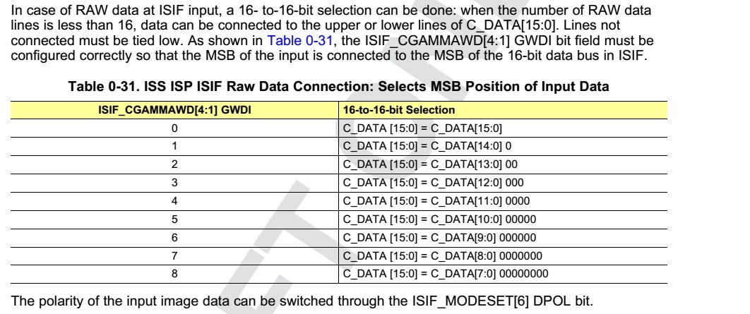
    The ISIF has 16 input data lines (C_DATA[15:0]) and if the senor is providing fewer than 16 bit input then you can connect the 12 sensor data lines starting from any of the ISIF data lines and then program the ISIF_CGAMMAWD[4:1] GWDI field appropriately.

    Pl. check the ISS doc more details:


    regards,

    Anand

  • Hi Anand,

    That's what I thought originally - but then at a closer look, if I want RAW data - nothing to do with any GAMMA or any Pipes, but data coming straight from the sensor, this is not a viable solution.

    I used the DCC tool and set all of the possible combinations for the ISIF_CGAMMAWD, and none of them gives us a correct image.

    I quote from SPRUFG8C–March 2009–Revised November 2010 - page 85. For RAW data, it seems that 4 wires should be left unconnected.

    If the wires to the sensor are connected incorrectly, is there any other way to fix this?

    Thanks,

    Mechi