This thread has been locked.

If you have a related question, please click the "Ask a related question" button in the top right corner. The newly created question will be automatically linked to this question.

Problems with HexAIS_OMAP-L138 file converter

Other Parts Discussed in Thread: OMAP-L138, OMAPL138, OMAP-L132

Hello,

Using OMAP-L138 LCDK and CCS v6.  I am able to succesfully use AISgen to convert the .OUT file (compiled ARM application from CCS) into an AIS file, and load it onto the dev-kit NAND and run it on the ARM. 

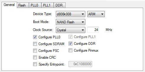
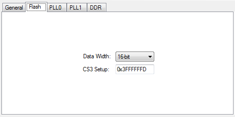
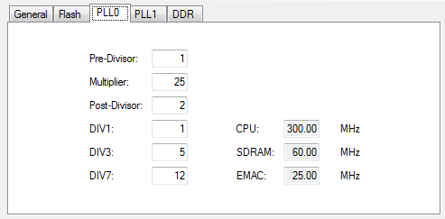
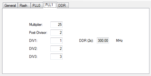
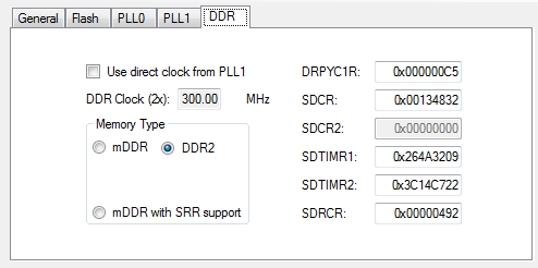
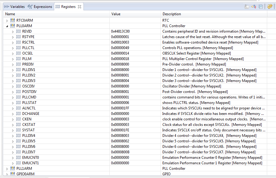
However, we need a command line version of AISgen so compiling and converting to AIS format can be automated with scripts.  When I try to do the same thing with, HexAIS_OMAP-L138, the resulting AIS file has problems and doesn't run.  One problem might be that to use HexAIS_OMAP-L138 I first have to convert the OUT file to a BIN file, using the out2rprc tool.  Don't have to do this conversion with AISgen.  In any case, when I use a HEX editor to compare the AIS file output by AISgen vs. the AIS file output by HexAIS_OMAP-L138, I see a lot of significant differences, to the point where I can't even match up parts of the one file to the other.  I tried to set up the INI file to match all the settings I used in AISgen, but I don't know if I'm doing it right because I can't find any documentation for HexAIS_OMAP-L138 or the INI files, other than the one INI example file from http://processors.wiki.ti.com/index.php/File:OMAP-L138_inifiles.zip

Does anyone know what could be going wrong?  Are there example INI files for HexAIS_OMAP-L138 that are specifically configured for the LCDK?

Thanks,

- Matt.

  • Dear Matthew,
    You can refer to the following readme.txt documentation, says that you can use .out file directly for AIS conversion through HexAIS_OMAPL138 tool.

    C:\ti\OMAP-L138_FlashAndBootUtils_2.40\OMAP-L138\GNU\AISUtils\readme.txt

    Can you please try to convert without doing rprc ?
  • Thanks for the response Titus,

    I found the readme, and I used HexAIS_OMAPL138 directly the OUT file, but it still didn't work.  When I use AISgen, the resulting AIS file is much smaller than the original OUT file, but when I use HexAIS_OMAPL138, the AIS file is only slightly smaller.  Is there some way to make HexAIS_OMAPL138 process files just like AISgen does?

    thanks.

  • Can you post some screenshots from AISgen as well as your corresponding ini file for HexAIS?
  • Sure, and thanks in advance for any insights you can offer.

    For the settings in AISgen, I'm using the OMAPL138_LCDK_AISGen_Config file that came with it.  I'll paste the contents here in case you don't have it handy:

    Boot Mode=NAND Flash

    Boot Speed=115200

    Flash Width=1

    Flash Timing=3ffffffd

    Configure Peripheral=False

    Configure PLL0=True

    Configure SDRAM=False

    Configure PLL1=True

    Configure DDR2=True

    Configure LPSC=False

    Configure Pinmux=False

    Enable CRC=False

    Specify Entrypoint=False

    Enable Sequential Read=False

    Use 4.5 Clock Divider=False

    Use DDR2 Direct Clock=False

    Use mDDR=False

    ROM ID=3

    Device Type=0

    Input Clock Speed=24

    Clock Type=0

    PLL0 Pre Divider=1

    PLL0 Multiplier=25

    PLL0 Post Divider=2

    PLL0 Div1=1

    PLL0 Div3=5

    PLL0 Div7=12

    PLL1 Multiplier=25

    PLL1 Post Divider=2

    PLL1 Div1=1

    PLL1 Div2=2

    PLL1 Div3=3

    Entrypoint=c1080000

    SDRAM SDBCR=0

    SDRAM SDTMR=0

    SDRAM SDRSRPDEXIT=0

    SDRAM SDRCR=0

    DDR2 PHY=c5

    DDR2 SDCR=134832

    DDR2 SDCR2=0

    DDR2 SDTIMR=264a3209

    DDR2 SDTIMR2=3c14c722

    DDR2 SDRCR=492

    LPSC0 Enable=

    LPSC0 Disable=

    LPSC0 SyncRst=

    LPSC1 Enable=13+

    LPSC1 Disable=

    LPSC1 SyncRst=

    Pinmux=

    App File String=

    AIS File Name=


    And here are the resulting screenshots:

    And here is the ini file I made for HexAIS (I'm not too worried about the DDR stuff, because my linker command file for the projects specifies to load the ARM application into shared RAM in the OMAP, not into the DDR).  Now, the resulting AIS file is very close in file size to the AIS generated by AISgen, but the one from HexAIS still doesn't work when I load it into the dev-board NAND and try to run it:

    ini file:

    ; General settings that can be overwritten in the host code
    ; that calls the AISGen library.
    [General]

    ; SPIMASTER,I2CMASTER,EMIFA,NAND,EMAC,UART,PCI,HPI,USB,MMC_SD,VLYNQ,RAW
    BootMode=NAND
    busWidth=16

    ; NO_CRC,SECTION_CRC,SINGLE_CRC
    crcCheckType=NO_CRC

    [PLL0CONFIG]
    PLL0CFG0 = 0x00190102
    PLL0CFG1 = 0x0001050C

    [PLL1CONFIG]
    PLL1CFG0 = 0x19020102
    PLL1CFG1 = 0x00000003


    [EMIF3DDR]
    PLL1CFG0 = 0x19020102
    PLL1CFG1 = 0x00000003
    DDRPHYC1R = 0x000000C5
    SDCR = 0x00134832
    SDTIMR = 0x264A3209
    SDTIMR2 = 0x3C14C722
    SDRCR = 0x00000492
    CLK2XSRC = 0x00000000


    [INPUTFILE]
    USEENTRYPOINT=NO
    FILENAME=boot.out
    ;LOADADDRESS=0xC1080000
    ;ENTRYPOINTADDRESS=0xC1080000

    Thanks again,

    Matt. 

  • I think your issue is relatively minor here.  It looks to me like you have not accounted for some slight differences in data entry between the GUI tool (AISgen) and the command line tool (HexAIS).  In particular, the GUI takes care of the "minus one" required by some fields.  Here's a quote from Section 5.3.2 "Phase-Locked Loop (PLL) Setup" of SPRAB41E "Using the OMAP-L132/L138 Bootloader":

    "The multiplier and divider values that you enter are the actual multiplication and division

    factors (x), not the values that get programmed into the corresponding PLL registers (x - 1)."

    HexAIS in contrast requires you to enter the register values directly.

    Matthew Mulvey said:

    [PLL0CONFIG]
    PLL0CFG0 = 0x00190102
    PLL0CFG1 = 0x0001050C

    [EMIF3DDR]
    PLL1CFG0 = 0x19020102
    PLL1CFG1 = 0x00000003
    DDRPHYC1R = 0x000000C5
    SDCR = 0x00134832
    SDTIMR = 0x264A3209
    SDTIMR2 = 0x3C14C722
    SDRCR = 0x00000492
    CLK2XSRC = 0x00000000

    I think these should be:

    [PLL0CONFIG]
    PLL0CFG0 = 0x00180001
    PLL0CFG1 = 0x0000040B

    [EMIF3DDR]
    PLL1CFG0 = 0x18010001
    PLL1CFG1 = 0x00000002

    As a sanity check I recommend using the OMAP-L1x debug gel files to compare your PLL settings between these two setups:

    http://processors.wiki.ti.com/index.php/OMAP-L1x_Debug_Gel_Files


  • Thanks for the response Brad. I changed those values as you suggested. Unfortunately, it still doesn't end up working when I try to run the resulting AIS. It seems like there is something fundamentally different between the way AISgen and HexAIS process the OUT files. The two AIS files come from the same OUT file, but they end up with significant differences. For example, by comparing both in a hex editor, I can see that the one output by AISgen has six "section load" commands in it, while the one output by HexAIS ony has four. How could the files end up so different?
    Thanks again for any suggestions you can offer about how I can proceed.
  • I don't have insight into the underlying implementations to comment there. The place I think we need to focus (first) is on the corresponding PLL and DDR setup. Can you create a "dummy" program that consists of a simple while(1) loop? I'd like to have a consistent environment where you allow the bootloader to run and then you connect with CCS and use the gel file I mentioned previously to print out some corresponding debug info related to the clocking.
  • I'm kind of new to all this, so I'm not sure how to do that. I made the dummy program with the while(1) loop, used HexAIS to convert to AIS, loaded it onto NAND and ran it, but I'm not sure how to connect after its running. I can connect to the target by connecting the debug probe and hitting debug in CCS. But if I understand correctly, when I do that, it's going to stop the program that was loaded out of NAND, and re-run it straight from CCS, is that right? So anything I see after connecting won't tell me anything about the executable that came out of HexAIS, correct?
  • If you go to View -> Target Configurations you should be able to right-click on your target configuration and do "launch" (or something along those lines). This will launch the debugger but does not connect to any cores or download any code. Then in the debug window you can right-click on the ARM9 and click "connect". This will connect, but will not download any code. At this point you can now view registers in memory windows and/or run the gel file from the page I mentioned.
  • Thanks, I finally got a chance to get back to this. I was able to load the AIS file generated by hexAIS and connect to see the registers. The AIS scripts in the file do seem to work, because I can see that the PLL registers match what was in the INI file, and I can insert an AIS command into the file which writes test data to the DDR, and I can see that it works after connecting to target and browsing DDR memory in CCS. screen-cap is attached that shows PLL regs. However, the ARM application still does not run. It only runs if I generate the AIS file from AISgen, but not if it comes from hexAIS. The AIS commands in both files that configure registers seem to be the same and work the same in both AIS files. But the ARM application sections embedded in the file end up different with hexAIS, and there are less sections in the file. In other words, hexAIS seems to be messing up the ARM executable sections in the AIS file, or converting to some other format. Not sure what to try next, but any ideas would be appreciated.

    thanks again,

    Matt.

  • 1. Create a "do nothing" ARM application (i.e. I don't want your application to mess with the state of anything!
    2. Use both of the tools to create a file that can be flashed.
    3. Run the version from HexAIS. Use the "Run All" command from this gel file: processors.wiki.ti.com/.../OMAP-L1x_Debug_Gel_Files
    4. Copy the output from above into HexAIS.txt.
    5. Run the version from AISgen. Use the "Run All" command from this gel file: processors.wiki.ti.com/.../OMAP-L1x_Debug_Gel_Files
    6. Copy the output from above into AISgen.txt
    7. Zip the files and attach here.
  • I downloaded the get file at your link, but I'm having some trouble with it.  When I use the "Runn all" command and the gel file runs, I was getting a "Run_All() cannot be evaluated." error.  Looked online and discovered the "?" operators were causing the problem as seen here:

    https://e2e.ti.com/support/dsp/omap_applications_processors/f/42/t/442118

    So I fixed those, and now the gel file runs a little further, but I'm still getting an error.  Here is the output:

    ARM9_0: GEL Output:

    ---------------------------------------------

    ARM9_0: GEL Output: | Device Information |

    ARM9_0: GEL Output: ---------------------------------------------

    ARM9_0: GEL Output: DEV_INFO_00 = 0x1B7D102F

    ARM9_0: GEL Output: DEV_INFO_01 = 0x00000000

    ARM9_0: GEL Output: DEV_INFO_02 = 0x00000010

    ARM9_0: GEL Output: DEV_INFO_03 = 0x00000033

    ARM9_0: GEL Output: DEV_INFO_04 = 0x00000000

    ARM9_0: GEL Output: DEV_INFO_05 = 0x000003E0

    ARM9_0: GEL Output: DEV_INFO_06 = 0x00000080

    ARM9_0: GEL Output: DEV_INFO_07-DEV_INFO_08-DEV_INFO_09-DEV_INFO_10-DEV_INFO_11-DEV_INFO_12 = 0-0-6510945-3-37-34

    ARM9_0: GEL Output: DEV_INFO_13,DEV_INFO_14,DEV_INFO_15,DEV_INFO_16 = 3,0,0,8398

    ARM9_0: GEL Output: -----

    ARM9_0: GEL Output: DEV_INFO_17 = 0x00030003

    ARM9_0: GEL Output: DEV_INFO_18 = 0x00000000

    ARM9_0: GEL Output: DEV_INFO_19 =ARM9_0: GEL Output: 0ARM9_0: GEL Output: 0ARM9_0: GEL Output: 0ARM9_0: GEL Output: 0ARM9_0: GEL Output: 0ARM9_0: GEL Output:

    ARM9_0: GEL Output: -----

    ARM9_0: GEL Output: DEV_INFO_20 = 0x00000000

    ARM9_0: GEL Output: DEV_INFO_21 = 0x00000000

    ARM9_0: GEL Output: DEV_INFO_22 = 0x30303864

    ARM9_0: GEL Output: DEV_INFO_23 = 0x3830306B

    ARM9_0: GEL Output: -----

    ARM9_0: GEL Output: DEV_INFO_24 = 0x03022025

    ARM9_0: GEL Output: DEV_INFO_25 = 0x00635961

    ARM9_0: GEL Output: DEV_INFO_06 = 0x00000080

    ARM9_0: GEL Output: DEV_INFO_26 = 0x419C0003

    ARM9_0: GEL Output:

    ARM9_0: GEL Output: ---------------------------------------------

    ARM9_0: GEL Output: | BOOTROM Info |

    ARM9_0: GEL Output: ---------------------------------------------

    ARM9_0: GEL Output: ROM ID: d800k008

    ARM9_0: GEL Output: Silicon Revision 2.1

    ARM9_0: GEL Output: Boot pins: 16

    ARM9_0: GEL Output: Boot Mode: NAND 16

    Run_All() cannot be evaluated.

    cannot right shift void

    at (BLCfgStruct>>8) [OMAPL1x_debug.gel:197]

    at Print_ROM_Info() [OMAPL1x_debug.gel:65]

    at Run_All()

    ------------------------------------------------------------------

    Not sure how to fix this one.  Any ideas?

    thanks.


  • Do the PLL and PSC functions work? Those were the main ones I was interested in.
  • Yes, when I run those functions by themselves, they seem to work.  Output is attached. The output of these tests seems to be identical between the AISgen version and the hexAIS one.gel_output.zip

  • Can you attach the resulting ais files too? I would like to compare.
  • Sure, AIS files are attached.  All three came from the same .out file.  

    For "boot_hexAIS.ais" the last few lines of the hexAIS INI file are:

    [INPUTFILE]

    USEENTRYPOINT=YES

    FILENAME=boot.out

    LOADADDRESS=0x80000000

    ENTRYPOINTADDRESS=0x80000000

    For "boot_hexAIS2.ais" the last few lines are:

    [INPUTFILE]

    USEENTRYPOINT=NO

    FILENAME=boot.out

    ; LOADADDRESS=0x80000000

    ; ENTRYPOINTADDRESS=0x80000000

    That is the only difference in generating them, but you can see "boot_hexAIS.ais" is much larger.

    AIS_files.zip

  • I used the perl script from this page to get a rough idea of what's happening in the AIS file:

    http://processors.wiki.ti.com/index.php/Manually_Patch_AIS_File_using_Perl_Script

    I'm attaching the decoded summary in case you are not familiar with Perl: decoded-ais.zip

    It looks to me like HexAIS2 is VERY similar to the AISgen output.  The major differences are:

    1. AISgen appears looks as if it loaded TWO executables.  There is something loaded to address 0xFFFF0B20, which is ARM's local RAM.  Any idea what this is?  I think AISgen allows you to combine multiple out files into a single AIS image.  Are you doing something along those lines?
    2. The HexAIS2 is jumping to address 0x00000000 at the end which is clearly wrong.

    Related to item #2 above, can you change USEENTRYPOINT to be "yes" in your HexAIS2 configuration?  (Keep the other lines commented out.)  This feature is telling the AIS interpreter to use the entry point that is embedded in your out file.

  • I am not setting AISgen to combine multiple .out files. There is just the one .out file.
    Not sure why anything would get loaded to 0xFFFF0B20. If I understand correctly, AISgen extracts the load addresses from the .out file, which in turn gets those addresses from the cmd file used by the linker when building? If I'm understanding that correctly, then the only load addresses used should be in the 0x80000000 range, because that's what is in the cmd file (below).
    The "boot_hexAIS.ais" file that I sent in my last message was generated with USEENTRYPOINT=YES. This results in a much larger AIS file. That difference in the INI file is the only difference in how "boot_hexAIS.ais" and "boot_hexAIS2.ais" were generated, but somehow the resulting AIS files seem very different.
    Here is the linker cmd file used for all cases:
    /****************************************************************************/
    /* boot.cmd - Linker command file for StarterWare bootloader */
    /****************************************************************************/
    -stack 0x2000 /* SOFTWARE STACK SIZE */
    -heap 0x1000 /* HEAP AREA SIZE */
    -e Entry/* SPECIFY THE SYSTEM MEMORY MAP */MEMORY{
    ONCHIP_RAM : org = 0x80000000 len = 0x20000 /* L3 RAM */}
    /* SPECIFY THE SECTIONS ALLOCATION INTO MEMORY */SECTIONS{ .init : {
    system_config.lib<init.obj> (.text)
    } load > 0x80000000
    .text : load > ONCHIP_RAM /* CODE */
    .data : load > ONCHIP_RAM
    .bss : load > ONCHIP_RAM /* GLOBAL & STATIC VARS */
    RUN_START(bss_start), RUN_END(bss_end)
    .const : load > ONCHIP_RAM /* SOFTWARE SYSTEM STACK */
    .cinit : load > ONCHIP_RAM /* SOFTWARE SYSTEM STACK */
    .stack : load > 0x8001E000 /* SOFTWARE SYSTEM STACK */
    }
  • Matthew Mulvey said:

    [INPUTFILE]

    USEENTRYPOINT=YES

    FILENAME=boot.out

    LOADADDRESS=0x80000000

    ENTRYPOINTADDRESS=0x80000000

    For "boot_hexAIS2.ais" the last few lines are:

    [INPUTFILE]

    USEENTRYPOINT=NO

    FILENAME=boot.out

    ; LOADADDRESS=0x80000000

    ; ENTRYPOINTADDRESS=0x80000000

    According to your post above there were 3 differences.  I'm asking you to change 1 of the 3 (USEENTRYPOINT).  Set USEENTRYPOINT=YES and leave the other lines commented out.

  • Okay, that did the trick! Thanks very much for you help.
    I was taking it as a given that if USEENTRYPOINT=YES, then addresses would need to be specified for LOADADDRESS and ENTRYPOINTADDRESS in the ini file. Never occured to me USEENTRYPOINT could be YES without addresses specified.
    Now, with this change to the INI, hexAIS generates a file that seems to be the same as "boot_hexAIS2.ais", except that the last line jumps to 0x80000000.
    When I flash it into the NAND and run it, the ARM application works as expected.
    Thanks very much again for you help.
    Its hard to piece together these things from the documentation, so this forum really helps.
  • Awesome! Please post your final parameters and let's go ahead and mark that as "verified"!

  • Sure, I can post parameters, but not sure what that would include. INI file? .out and .ais files?
    I won't be able to post any of that kinds of stuff until I get in to work tomorrow.
    Will do it then.Thanks again!
  • The ini file should be sufficient. Glad we figured it out. Thanks!
  • final INI file is attached.

    https://e2e.ti.com/cfs-file/__key/communityserver-discussions-components-files/791/OMAPini.ini