This thread has been locked.

If you have a related question, please click the "Ask a related question" button in the top right corner. The newly created question will be automatically linked to this question.

Cold or warm reset by external power supervisior IC

Other Parts Discussed in Thread: AM3352

Dear experter.

I am using AM3352 for my application. And the main power supervisior ic is MAX690.

The MAX690 has functions of watchdog and power supervisior in one package.

For check power, I connect the reset output signal to POWERONRSTN on AM3352.

When the power is up, AM3352 operates well.

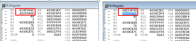
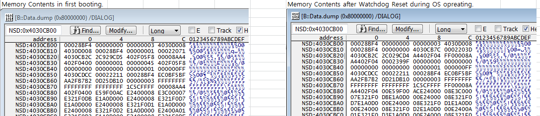
But when ther reset output by watchdog, that is, the power and clock is in normal state, the boot sequence goes to fail.

I use the SPI Flash for bootloader.

For test, when the reset signal is sent to AM3352 on Serial boot mode (SYS_BOOT[4:0] = 00001). the CPU start up normally.

But I change SYS_BOOT[4:0] to 10110b, the CPU stops and does nothing.

I check power and clock. All are normal state.

What are the check points for fix this problems.

Regards

  • Dear experter.

    I find more something strange opertion.
    The operating system of my CPU is VxWorks.
    If OS does not start, the reset operation does well.
    But after VxWorks starting, the reset operation does not start and CPU state goes data abort exception.

    I think VxWorks change some register value from default to other value. and then during reset operation the changed register does not go default value.

    Is there any idea?
  • Hi,

    VxWorks is a third-party OS and is not supported by TI. Therefore we cannot say whether this behavior is caused by register changes caused by software. What I can suggest is that you check the state of the SPI signals in both cases - normal boot and failed boot.
  • Another thing to check is the contents of control_status register (if possible) and SYSBOOT pins in both cases. It's possible that the SYSBOOT pins have changed their state already when you try a watchdog reset, and correct value is not latched in the processor.
  • Thanks you for your relpy.

    OK, I understand and agree with you about OS. But I don't think this is problem from VxWorks totally.
    I suppose, In AM3352, there is any internal function block which does not go to default state by PORz signal input in normal power condition.
    But I don't know what is that?

    If I know the module, I think, I can fix this more easier.

    And I have checked SPI Flash signal. In abnormal state, the AM3352 does not output SPI0 Clock.


    If you give hint or tip, I will appreciate your help.

    Best regards
    Hongseon-Ahn

  • Please read my second post and check.
  • Thanks your for your hint.

    I have checked control_status_reginter (0ffset=0x40h), The value in register is equal to dip switch status, SPI Boot mode.
    For checking, I used emulator debugger Trace32.
    When I send reset signal to AM3352 using debugger, there is same operation, that is, booting failure.


    Best regards
    Hongseon Ahn
  • How is the processor Warm Reset connected?
  • I am very thanks for reply.

    I have been conducting to find the reason of misoperationg. And I found something strange.

    Left is normal state. And Right is mis-operating state.

    The register value R0, R1 shows difference.

    So I think this is the reason that CPU occured exception with data abort in OP code stage.

    But I don't know reason.

    Please give hint for this.

    Best regards

    Hongseon Ahn

  • Hi

    There is one more question and I think this is very important phenomenon.

    With external watchdog reset signal in normal power and PLL state,  there is no change in OCMC contents.

    And boot program in AM3352 use data in OCMC.

    Below is capture contents by emulator.

    Left is capture when AM3352 is in power on reset.  And right is capture when AM3352 is in reset state aftwer os running.

    0x4030CB28 data is chaged from 0x402F05F8 to 0xA4402F04.

    The data was chaged by OS.

    But in this state, External watchdog reset can not change to default like left. The data in pointer 0x4030CB28 can be only restored  by Power Off/ON.

    Furthermore AM3352 boot program use this data without change. So MCU do not operate with watchdog in this situation, that is, MCU goes down and has exception data abort.  

    In addition, I modified directly this pointer to zero or other value in debugging environment. But After reset(didn't change power and pll), the value restored to upper. Data modified by me was disappeared.

    So I suppose, This area maybe mirrors some CPU register. I don't know whether I am right.

    There is no more information about OCMC.

    If you has any idea about obove, please inform of me.

    Best regards

    Hongseon Ahn

  • Hongseon Ahn said:

    I have been conducting to find the reason of misoperationg. And I found something strange.

    Left is normal state. And Right is mis-operating state.

    The register value R0, R1 shows difference.

    So I think this is the reason that CPU occured exception with data abort in OP code stage.

    Looking at the boot ROM disassembly in a AM3352 with boot ROM version 0x2203, around PC 0x21ff6 where the data abort occurs shows the following:

    00021ff2:   6831                ldr        r1, [r6]
    00021ff4:   CC01                ldm        r4!, {r0}
    00021ff6:   6008                str        r0, [r1]
    00021ff8:   6830                ldr        r0, [r6]
    00021ffa:   1D00                adds       r0, r0, #4
    00021ffc:   1E6D                subs       r5, r5, #1
    00021ffe:   F01505FF            ands       r5, r5, #0xff
    00022002:   6030                str        r0, [r6]
    00022004:   D1F5                bne        #0x21ff2

    i.e. the instruction at address 0x21ff6 is storing the contents of r0 in the address in r1. In the normal state the address r1 is 0x402f0400 which is the start address of the internal SRAM. In the mis-operating state the address r1 is 0xa4402f04. 0xa4402f04 is in the address range of EMIF0 SDRAM, and will cause the boot ROM to suffer a data abort as the EMIF0 SDRAM isn't enable when the boot ROM is running.

    I think what may be happening is that in the mis-operating state the boot ROM starts to read the image header from SPI flash but there is an spurious initial byte read, which corrupts the destination address of the image from 0x402f0400 to 0xa4402f04 (the destination address is read after the image size, so a corrupt image size was probably also read). This then causes the boot ROM to suffer a data abort when attempts to write the image to address 0xa4402f04 which is not in the internal SRAM.

    Maybe after a warm reset the SPI flash is in a different state, which causes the problem. Can you try and use a LSA / scope to watch the initial SPI flash transactions after a cold and warm reset to identify any differences?

  • I received the following reply in an email from the Forum, but since it isn't showing up am repeating it:

    Hongseon Ahn said:

    Thanks you for your support.

    Yes, You are right about that. The fail point is above address. And I have been finding more reasons.

    I found one more reason about memory error at 0x4030cb24.

    During power on reset, ths spi clk consists of 8 bit data length. But after watchdog reset, the spi clock has 32bit data length.

    I don't know why that was happened. OS does not set to 32bit to MCSPI_CH0CONF register.

    When the cpu run without VxWorks OS, above was not happened. But with OS operating, spi fail was occured.

    I have no idea about relation with OS and SPI register.

    I think, if there is change value in SPI control register by OS, CPU must restore default value after reset.

    It's not easy to catch way to debug problem.

    Best regards

    Hongseon Ahn

  • I am very thank you for support.

    I finally found the reason of this problem. The problem is from SPI flash.

    The flash memory in my system has 256MBit sizes. So the driver of VxWorks was set to 4 Byte Address interface with Bank Setting.

    When Power-ON reset, the bank setting in flash memory is reset to zero. But after boot up, OS chages to one (use).

    If watch-dog reset signal was given from supervision without power change. the register value in flash does not change.

    But by watchdog the AM3352 enter boot mode, the default SPI byte mode of CPU during boot up is 3 byte address mode.

    So first data, program vector and size data, can not be readable correctly.

    This makes exception with data abort.

    I have changed OS driver and test. Watchdog reset operates well.

    Thank you for any help.

    Best regards

    Hongseon Ahn