This thread has been locked.

If you have a related question, please click the "Ask a related question" button in the top right corner. The newly created question will be automatically linked to this question.

Am5728 CLSR Registers vs TRM?

Other Parts Discussed in Thread: AM5728, SYSCONFIG

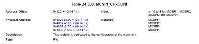
Starting to look at developing a MCSPI driver for the AM5728.  I have processor_sdk_rtos_am57xx_2_00_00_00 which includes pdk_am57xx_1_0_0.  In the packages\ti\csl folder I find the file cslr_mcspi.h which seems to define the registers and fields for the MCSPI, but starting with SOFTRESET it does not seem to match the TRM, AM572x_SR1.1_TRM_vD.pdf.

For example, from the cslr_mcspi.h

/* HL_SYSCONFIG */

#define CSL_MCSPI_HL_SYSCONFIG_IDLEMODE_MASK                    (0x0000000CU)
#define CSL_MCSPI_HL_SYSCONFIG_IDLEMODE_SHIFT                   (2U)
#define CSL_MCSPI_HL_SYSCONFIG_IDLEMODE_RESETVAL                (0x00000002U)
#define CSL_MCSPI_HL_SYSCONFIG_IDLEMODE_SMARTIDLEWAKEUP         (0x00000003U)
#define CSL_MCSPI_HL_SYSCONFIG_IDLEMODE_FORCEIDLE               (0x00000000U)
#define CSL_MCSPI_HL_SYSCONFIG_IDLEMODE_NOIDLE                  (0x00000001U)
#define CSL_MCSPI_HL_SYSCONFIG_IDLEMODE_SMARTIDLE               (0x00000002U)

#define CSL_MCSPI_HL_SYSCONFIG_RSVD_MASK                        (0xFFFFFFF0U)
#define CSL_MCSPI_HL_SYSCONFIG_RSVD_SHIFT                       (4U)
#define CSL_MCSPI_HL_SYSCONFIG_RSVD_RESETVAL                    (0x00000000U)
#define CSL_MCSPI_HL_SYSCONFIG_RSVD_MAX                         (0x0fffffffU)

#define CSL_MCSPI_HL_SYSCONFIG_SOFTRESET_MASK                   (0x00000001U)
#define CSL_MCSPI_HL_SYSCONFIG_SOFTRESET_SHIFT                  (0U)
#define CSL_MCSPI_HL_SYSCONFIG_SOFTRESET_RESETVAL               (0x00000000U)
#define CSL_MCSPI_HL_SYSCONFIG_SOFTRESET_RESETDONE              (0x00000000U)
#define CSL_MCSPI_HL_SYSCONFIG_SOFTRESET_NOACTION               (0x00000000U)
#define CSL_MCSPI_HL_SYSCONFIG_SOFTRESET_SOFTRESET              (0x00000001U)
#define CSL_MCSPI_HL_SYSCONFIG_SOFTRESET_RESETONGOING           (0x00000001U)

#define CSL_MCSPI_HL_SYSCONFIG_FREEEMU_MASK                     (0x00000002U)
#define CSL_MCSPI_HL_SYSCONFIG_FREEEMU_SHIFT                    (1U)
#define CSL_MCSPI_HL_SYSCONFIG_FREEEMU_RESETVAL                 (0x00000000U)
#define CSL_MCSPI_HL_SYSCONFIG_FREEEMU_EMUDIS                   (0x00000001U)
#define CSL_MCSPI_HL_SYSCONFIG_FREEEMU_EMUEN                    (0x00000000U)

#define CSL_MCSPI_HL_SYSCONFIG_RESETVAL                         (0x00000008U)

That tells me that SOFTRESET is bit 0.

From the TRM,

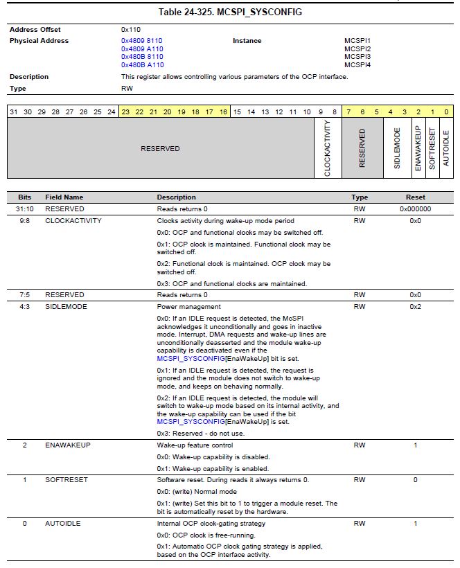
The other fields also don't agree.  I feel like cslr_mcspi.h is not the correct file for the AM5728. 

Can someone explain what I am doing wrong here?  Is there an update I am missing maybe?  I also feel like there should be some higher level of integration available for this.  I noticed in the spi_test_idkAM572x.cfg file they load a spi driver...

/* Load the spi package */
var socType          = "am572x";
var Spi              = xdc.loadPackage('ti.drv.spi');
Spi.Settings.socType = socType;

Should I not be writing a low level driver?  When I asked this question previously I felt like the drivers did not exist, but now I am thinking they do.  For example, it seems like pdk_am57xx_1_0_0\packages\ti\drv\spi\SPI.h probably offers me all I need to use the MCSPI.

Thanks.

  • So, I have found the document SPI_LLD_UserGuide.pdf and it would seem to say that everything I need is already provided. Great. However, one wrinkle.

    We want to use one SPI instance to talk to two devices by using two (of the four) chip selects. I see in the spiInitCfg structure in the file soc\am572x\SPI_soc.c that the chNum parameter is set to MCSPI_CHANNEL_0. I assume I can change that to any of the 4 channels available per our design. However, we want to use more than one channel at a time. This would seem to imply to me that we would need to basically do the entire sequence as shown in section 6.3 of the users guide for every transfer, changing the chNum parameter before calling SPI_init().

    Perhaps I could modify the driver and pass chNum into the SPI_transfer() function?
  • I will ask the RTOS team to comment.
  • Hi Chris,

    I think your not looking at the correct SYSCONFIG register in the SPEC. The McSPI spec has a MCSPI_HL_SYSCONFIG and MCSPI_SYSCONFIG. The CSL code you have provided is for the HL_SYSCONFIG register and the TRM screenshot is for the SYSCONFIG register. Hope this clarifies the issue.  Also as you noticed already, we have provided a McSPI LLD driver in the release that you can use for your application.

    I will take a look at the mutlichannel implementation in the LLD and let you know if the driver can support your usecase.

    Regards,

    Rahul

    PS: I have confirmed that both the bits can be used to reset the McSPI module.

  • Rahul,

    Thanks for the clarification on the HL_SYSCONFIG vs SYSCONFIG.

    Have you had a chance to look into the ability to use two chip selects with a single SPI Master Module. We have been looking at the driver code and the usage of "channel" is pretty confusing. We believe there are 4 MCSPI modules which support 4 chip selects (channels?) each. But we don't see how you would associate which chip select is active with a particular instance of the module or how you would use two or more chip selects with a module.
     
    We also noticed something else concerning with regards to "channels". If you look at the TRM, the note in Figure 24-79 (our use case) says "In this case m=[1,3]." That implies to me that if I want to use a MCSPI module with two chip selects, I can only do so on modules 1 and 3. That could be a big limitation for us as those pins might not be available depending on what other resources we are using (ie GPMC).

    To re-iterate our use case, we'd like to use 2 MCSPI Modules, MCSPI1 and MCSPI2, each with 2 chip selects. As we are doing the board schematics now, we need to know if this is a possibility.

    Thanks,

    Chris

  • I think I'm a bit closer to the answer now that I realize the text in the TRM is misleading.  For example,

    It says for the Index "x = 0 to 3 for MCSPI1, MCSPI2, MCSPI3, MCSPI4"  If it said "x = 0 to 3 for the channel per MCSPI Instance" that would have been more clear to me.

    What the code does not seem to provide is a way to specify the channel when setting up the channel.  I think that is done via the chNum field in the SPI_v1_HWAttrs structure.  SPI_v1_HWAttrs is hardcoded in SPI_soc.c as spiInitCfg.  I don't see a function to modify that structure, so I guess we will have to access it manually. 

    So, I think the process to open two instances of one SPI module with two chip selects might be this....

    SPI_Init();

    Setup SPI_Params for SPI1/CH1

    Setup SPI_v1_HWAttrs for SPI1/CH1

    handle1 = SPI_Open()

    Setup SPI_Params for SPI1/CH2

    Setup SPI_v1_HWAttrs for SPI1/CH2

    handle2 = SPI_Open()

     Then we can call SPI_transfer using handle1 or handle2 as needed, but not at the same time obviously.

  • Christopher Peters said:
    We believe there are 4 MCSPI modules which support 4 chip selects (channels?) each.

    Correct.

    Christopher Peters said:
    But we don't see how you would associate which chip select is active with a particular instance of the module or how you would use two or more chip selects with a module.

    It's a fixed association, i.e. channel x corresponds to cs_x.  This info appears to be missing from the AM57xx TRM.  I have answered similar questions on other devices:

    https://e2e.ti.com/support/arm/sitara_arm/f/791/t/465014

    I filed a ticket to have this added to the AM57xx TRM.

    Christopher Peters said:
    We also noticed something else concerning with regards to "channels". If you look at the TRM, the note in Figure 24-79 (our use case) says "In this case m=[1,3]." That implies to me that if I want to use a MCSPI module with two chip selects, I can only do so on modules 1 and 3.

    I've asked the documentation team for clarification on that note.  I'm not aware of anything limiting that use case to specific modules.  I believe it should be usable for m=1,2,3,4 but I have asked for confirmation (and a clarification in a future TRM).

    Christopher Peters said:
    To re-iterate our use case, we'd like to use 2 MCSPI Modules, MCSPI1 and MCSPI2, each with 2 chip selects. As we are doing the board schematics now, we need to know if this is a possibility.

    That should be fine.  I'll follow-up with details from the TRM team as soon as I can.  It might take me a day.  Can you avoid the issue altogether by using McSPI1 and McSPI3, or do pin mux conflicts prevent that?

  • Christopher Peters said:

    I think I'm a bit closer to the answer now that I realize the text in the TRM is misleading.  For example,

    It says for the Index "x = 0 to 3 for MCSPI1, MCSPI2, MCSPI3, MCSPI4"  If it said "x = 0 to 3 for the channel per MCSPI Instance" that would have been more clear to me.

    You're absolutely correct.  I filed a ticket to get that fixed.  Thank you for mentioning it.

  • Thanks for the input Brad.

    Regarding using McSPI1 and McSPI3, according to our board designer there is a pinmux conflict with GPMC.
  • Chris,

    Your understanding is correct, you will need to create 2 handles with the appropriate channel number and  chips select and use the handles to drive that particular channel. The parameters as you specified need to modified in the SPI_v1_HWAttrs structure.

    SPI_soc.c file binds driver with hardware attributes on the board through SPI_config[] structure. This structure must be provided to the SPI driver. It must be initialized before the SPI_init() function is called and cannot be changed afterwards. The driver includes a default hardware attributes structure but it can be overridden by including that SPI_soc.c file into your application and modifying the instance based on your board requirement.

    When the linker builds your application it will link to the parameters from the SPI_soc.c file included in the application instead of the driver library.

    If you don`t want to do this from your application, you can choose to modify the SPI_v1_HWAttrs in the driver library to match your application board and rebuild the driver library so that there is no confusion due to over riden parameters.

    Regards,

    Rahul

  • Thank you for the input Rahul.

    Just to be 100% clear. I was thinking the spiInitCfg that is defined in SPI_soc.c was setup for one SPI_v1_HWAttrs per SPI Module instance, but in reality it does not need to be. Since we will be using 2 McSPI modules with 2 channels each, I will still have 4 entries, but there will be two for McSP1 and two for McSPI2 each defining the two channels (aka chip selects) we want to use. Since we will not be using the QSPI, we can drop that altogether. Whether we do that internally to the application or inside the driver library is a detail I can figure out later.

    Sounds good?
  • Christopher Peters said:
    Regarding using McSPI1 and McSPI3, according to our board designer there is a pinmux conflict with GPMC.

    The documentation team confirmed that was a hold-over from OMAP3.  It no longer applies and will be removed from the TRM.  Your plan to use McSPI1 and McSPI2 is fine.

  • Yes, that sounds good. You can remove the entries corresponding to McSPI3 and McSPI4 and have 2 entries for McSPI1 and McSPI2.

    Just some more clarification, the driver provides 2 libraries one which contains the SPIconfig for the SoC and one which is generic that requires the users to provide the board specific HWAttributes.

    Driver Library for ARM that includes the SPI_soc.c file can be found here:
    pdk_am57xx_1_0_0\packages\ti\drv\spi\lib\am572x\armv7\ti.drv.spi.am572x.aa15fg

    Driver Library for ARM that doesn`t include SPI_soc.c can be found here:
    pdk_am57xx_1_0_0\packages\ti\drv\spi\lib\armv7\ti.drv.spi.aa15fg

    If you use the second library, you can make then just make a copy the SPI_soc.c file to your application and replace the McSPI3 and McSPI4 entries with the a different channel on McSPI1/2.

    If you are not using QSPI driver, you don`t need to populate the QSPI parameters.

    Regards,
    Rahul
  • We are using this on the C66x with Sys/Bios. Hopefully everything we talked about stays the same. Thanks Brad and Rahul.
  • Sorry for making the assumption that you are doing this from the ARM.

    Yes, what we talked about stays the same from the DSP side as well.

    Regards,
    Rahul
  • No problem at all. My co-worker, Gerard Daubar, is also working on this same project, but his code will run on the ARM, so he will likely be doing some of the required config from the ARM, like clocks, and then I will be using the SPI from the DSP. He has been posting recently about the MMU configuration. Yes, this is going to be an interesting project. Thanks again.