Hi,
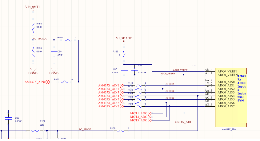
I currently trying to use the ADC module in the IDK kit, the example provided on starterware SDK 2.0.0.1 which uses the following pins ( AM437X_AIN1,AM437X_AIN0) . According to the provided schematic diagram :
AM437X_AIN0 is connected to external voltage(24 voltage source ) using voltage divider circuit which will result in an input of 1.17 volt voltage the would be always connected to the input pin .
when i try to use the provided example in the startercode the configuration of AFE (analouge front end) is setting the following register values as:
adcStepCfg.adcNegativeInpRef = TSCADC_NEGATIVE_REF_VSSA;
adcStepCfg.adcPositiveInpRef = TSCADC_POSITIVE_REF_VDDA;
adcStepCfg.adcNegativeInpChan = TSCADC_INPUT_CHANNEL1;
adcStepCfg.adcPositiveInpChan = TSCADC_INPUT_CHANNEL1;
adcStepCfg.enableXppsw = TRUE;
adcStepCfg.enableXnpsw = FALSE;
adcStepCfg.enableYppsw = FALSE;
adcStepCfg.enableXnnsw = TRUE;
adcStepCfg.enableYpnsw = FALSE;
adcStepCfg.enableYnnsw = FALSE;
adcStepCfg.enableWpnsw = FALSE;
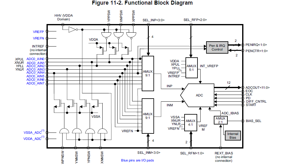
for The AFE block diagram in the following diagram:
I want to know the accuarte setting to AFE configuration ,so that the i/p to the analouge pins would equal zero voltage no extra bias.
If i use the provided example as it is it gives reading of 1173 mv at ADC_pin0 and ADC_pin1 wheter i had connected an i/p of ground to the pins or 3.3 voltage which is not correct .


