This thread has been locked.

If you have a related question, please click the "Ask a related question" button in the top right corner. The newly created question will be automatically linked to this question.

SPI is not working in AM335x

Other Parts Discussed in Thread: ADS1292

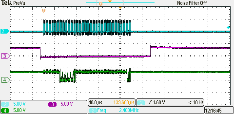
I’m Having trouble in getting SPI interface work with ADS1292.  Basically, what I’m facing is my SPI clock is’t coming.  


I searched through e2e forum and I got one link who had similar problem(http://e2e.ti.com/support/embedded/linux/f/354/p/340805/1194573#pi317016=1). Accordingly I did all my configuration. But still I don’t have luck. Could you be able to guide in this regard?


I understood that there is no readily available driver code for ADS1292. So trying to use available driver.


The changes are made in am335x-evmsk.dts


I have added the device tree for spi is as follow. (sdk 7.0 and kernel  version 3.12.10)


                                spi0_pins: pinmux_spi0_pins {

                                                pinctrl-single,pins = <

                                                                0x150 (PIN_OUTPUT| MUX_MODE0)    /* spi0_clk.spi0_clk */ //o/p

                                                                0x154 (PIN_OUTPUT_PULLUP| MUX_MODE0)    /* spi0_d0.spi0_d0 */ // o/p pull

                                                                0x158 (PIN_INPUT| MUX_MODE0)    /* spi0_d1.spi0_d1 */ // i/p

                                                                0x15c (PIN_OUTPUT_PULLUP| MUX_MODE0)    /* spi0_cs0.spi0_cs0 */ //o/p pull

                                                >;

                                };

-------

spi0: spi@48030000 {

                                compatible = "ti,omap4-mcspi";

                                #address-cells = <1>;

                                #size-cells = <0>;

                                reg = <0x48030000 0x400>;

                                interrupts = <65>;

                                ti,spi-num-cs = <2>;

                                pinctrl-names = "default";

                                pinctrl-0 = <&spi0_pins>;

                                ti,hwmods = "spi0";

                                clocks = <&dpll_per_m2_div4_ck>;

                                clock-names = "fck";

                                clock-frequency = <1000000>;         

                                dmas = <&edma 16

                                                &edma 17

                                                &edma 18

                                                &edma 19>;

                                dma-names = "tx0", "rx0", "tx1", "rx1";

                                status = "okay";

                                spidev:spidev@0{

                                                                                                compatible        = "spidev";

                                                                                                reg               = <0>;

                                                                                                spi-max-frequency = <10000000>;

                                                                };

  • Moving to the appropriate forum

    Regards,
    Gigi Joseph.
  • Hi,

    Which processor pins are you using for SPI? Please post pin numbers.
  • Processor pins are  A17,B17,B16,A16

  • OK, these are correct pins for SPI0. Two things to check:
    1. Check that the pinmux settings do not get overwritten by another pinmux later in your DTS file.
    2. This is secondary but important: SPI0_CLK must be pinmuxed as PIN_INPUT| MUX_MODE0, otherwise SPI receive will not work.
  • /*
     * Copyright (C) 2012 Texas Instruments Incorporated - http://www.ti.com/
     *
     * This program is free software; you can redistribute it and/or modify
     * it under the terms of the GNU General Public License version 2 as
     * published by the Free Software Foundation.
     */
    
    /*
     * AM335x Starter Kit
     * http://www.ti.com/tool/tmdssk3358
     */
    
    /dts-v1/;
    
    #include "am33xx.dtsi"
    #include <dt-bindings/pwm/pwm.h>
    
    / {
    	model = "TI AM335x EVM-SK";
    	compatible = "ti,am335x-evmsk", "ti,am33xx";
    
    	cpus {
    		cpu@0 {
    			/*cpu0-supply = <&vdd1_reg>; commented lahari */
    			cpu0-supply = <&dcdc2_reg>;
    		};
    	};
    
    	memory {
    		device_type = "memory";
    		reg = <0x80000000 0x10000000>; /* 256 MB */
    	};
    
    	am33xx_pinmux: pinmux@44e10800 {
    		pinctrl-names = "default";
    		//pinctrl-0 = <&clkout1_pin>;
    		pinctrl-0 = <&clkout1_pin &mmc1_pins &wlan_pins>;
    
    		/* ddr3_vtt_toggle: ddr3_vtt_toggle {
    			pinctrl-single,pins = <
    				0x164 0x7	/* ecap0_in_pwm0_out.gpio0_7, OUTPUT | MODE7 */
    			//>;
    		//};  ecap0_in_pwm0_out is used as mode0 */
    
    		lcd_pins_default: lcd_pins_default {
    			pinctrl-single,pins = <
    				0x20 0x01	/* gpmc_ad8.lcd_data16, OUTPUT | MODE1 */
    				0x24 0x01	/* gpmc_ad9.lcd_data17, OUTPUT | MODE1 */
    				0x28 0x01	/* gpmc_ad10.lcd_data18, OUTPUT | MODE1 */
    				0x2c 0x01	/* gpmc_ad11.lcd_data19, OUTPUT | MODE1 */
    				0x30 0x01	/* gpmc_ad12.lcd_data20, OUTPUT | MODE1 */
    				0x34 0x01	/* gpmc_ad13.lcd_data21, OUTPUT | MODE1 */
    				0x38 0x01	/* gpmc_ad14.lcd_data22, OUTPUT | MODE1 */
    				0x3c 0x01	/* gpmc_ad15.lcd_data23, OUTPUT | MODE1 */
    				0xa0 0x00	/* lcd_data0.lcd_data0, OUTPUT | MODE0 */
    				0xa4 0x00	/* lcd_data1.lcd_data1, OUTPUT | MODE0 */
    				0xa8 0x00	/* lcd_data2.lcd_data2, OUTPUT | MODE0 */
    				0xac 0x00	/* lcd_data3.lcd_data3, OUTPUT | MODE0 */
    				0xb0 0x00	/* lcd_data4.lcd_data4, OUTPUT | MODE0 */
    				0xb4 0x00	/* lcd_data5.lcd_data5, OUTPUT | MODE0 */
    				0xb8 0x00	/* lcd_data6.lcd_data6, OUTPUT | MODE0 */
    				0xbc 0x00	/* lcd_data7.lcd_data7, OUTPUT | MODE0 */
    				0xc0 0x00	/* lcd_data8.lcd_data8, OUTPUT | MODE0 */
    				0xc4 0x00	/* lcd_data9.lcd_data9, OUTPUT | MODE0 */
    				0xc8 0x00	/* lcd_data10.lcd_data10, OUTPUT | MODE0 */
    				0xcc 0x00	/* lcd_data11.lcd_data11, OUTPUT | MODE0 */
    				0xd0 0x00	/* lcd_data12.lcd_data12, OUTPUT | MODE0 */
    				0xd4 0x00	/* lcd_data13.lcd_data13, OUTPUT | MODE0 */
    				0xd8 0x00	/* lcd_data14.lcd_data14, OUTPUT | MODE0 */
    				0xdc 0x00	/* lcd_data15.lcd_data15, OUTPUT | MODE0 */
    				0xe0 0x00	/* lcd_vsync.lcd_vsync, OUTPUT | MODE0 */
    				0xe4 0x00	/* lcd_hsync.lcd_hsync, OUTPUT | MODE0 */
    				0xe8 0x00	/* lcd_pclk.lcd_pclk, OUTPUT | MODE0 */
    				0xec 0x00	/* lcd_ac_bias_en.lcd_ac_bias_en, OUTPUT | MODE0 */
    			>;
    		};
    
    		lcd_pins_sleep: lcd_pins_sleep {
    			pinctrl-single,pins = <
    				0x20 (PIN_INPUT_PULLDOWN | MUX_MODE7)	/* gpmc_ad8.lcd_data16 */
    				0x24 (PIN_INPUT_PULLDOWN | MUX_MODE7)	/* gpmc_ad9.lcd_data17 */
    				0x28 (PIN_INPUT_PULLDOWN | MUX_MODE7)	/* gpmc_ad10.lcd_data18 */
    				0x2c (PIN_INPUT_PULLDOWN | MUX_MODE7)	/* gpmc_ad11.lcd_data19 */
    				0x30 (PIN_INPUT_PULLDOWN | MUX_MODE7)	/* gpmc_ad12.lcd_data20 */
    				0x34 (PIN_INPUT_PULLDOWN | MUX_MODE7)	/* gpmc_ad13.lcd_data21 */
    				0x38 (PIN_INPUT_PULLDOWN | MUX_MODE7)	/* gpmc_ad14.lcd_data22 */
    				0x3c (PIN_INPUT_PULLDOWN | MUX_MODE7)	/* gpmc_ad15.lcd_data23 */
    				0xa0 (PULL_DISABLE | MUX_MODE7)		/* lcd_data0.lcd_data0 */
    				0xa4 (PULL_DISABLE | MUX_MODE7)		/* lcd_data1.lcd_data1 */
    				0xa8 (PULL_DISABLE | MUX_MODE7)		/* lcd_data2.lcd_data2 */
    				0xac (PULL_DISABLE | MUX_MODE7)		/* lcd_data3.lcd_data3 */
    				0xb0 (PULL_DISABLE | MUX_MODE7)		/* lcd_data4.lcd_data4 */
    				0xb4 (PULL_DISABLE | MUX_MODE7)		/* lcd_data5.lcd_data5 */
    				0xb8 (PULL_DISABLE | MUX_MODE7)		/* lcd_data6.lcd_data6 */
    				0xbc (PULL_DISABLE | MUX_MODE7)		/* lcd_data7.lcd_data7 */
    				0xc0 (PULL_DISABLE | MUX_MODE7)		/* lcd_data8.lcd_data8 */
    				0xc4 (PULL_DISABLE | MUX_MODE7)		/* lcd_data9.lcd_data9 */
    				0xc8 (PULL_DISABLE | MUX_MODE7)		/* lcd_data10.lcd_data10 */
    				0xcc (PULL_DISABLE | MUX_MODE7)		/* lcd_data11.lcd_data11 */
    				0xd0 (PULL_DISABLE | MUX_MODE7)		/* lcd_data12.lcd_data12 */
    				0xd4 (PULL_DISABLE | MUX_MODE7)		/* lcd_data13.lcd_data13 */
    				0xd8 (PULL_DISABLE | MUX_MODE7)		/* lcd_data14.lcd_data14 */
    				0xdc (PULL_DISABLE | MUX_MODE7)		/* lcd_data15.lcd_data15 */
    				0xe0 (PIN_INPUT_PULLDOWN | MUX_MODE7)	/* lcd_vsync.lcd_vsync, OUTPUT | MODE0 */
    				0xe4 (PIN_INPUT_PULLDOWN | MUX_MODE7)	/* lcd_hsync.lcd_hsync */
    				0xe8 (PIN_INPUT_PULLDOWN | MUX_MODE7)	/* lcd_pclk.lcd_pclk */
    				0xec (PIN_INPUT_PULLDOWN | MUX_MODE7)	/* lcd_ac_bias_en.lcd_ac_bias_en */
    			>;
    		};
    
    		i2c0_pins: pinmux_i2c0_pins {
    			pinctrl-single,pins = <
    				0x188 (PIN_INPUT_PULLUP | MUX_MODE0)	/* i2c0_sda.i2c0_sda */
    				0x18c (PIN_INPUT_PULLUP | MUX_MODE0)	/* i2c0_scl.i2c0_scl */
    			>;
    		};
    
    		uart0_pins: pinmux_uart0_pins {
    			pinctrl-single,pins = <
    				0x170 (PIN_INPUT_PULLUP | MUX_MODE0)	/* uart0_rxd.uart0_rxd */         //PULL_DISABLE ??
    				0x174 (PIN_OUTPUT_PULLDOWN | MUX_MODE0)		/* uart0_txd.uart0_txd */ //PULL_DISABLE ??
    			>;
    		};
    
    		clkout1_pin: pinmux_clkout1_pin {
    			pinctrl-single,pins = <
    				0x1b0 (PIN_OUTPUT_PULLDOWN | MUX_MODE3)		/* xdma_event_intr0.clkout1 */ //pull up
    			>;
    		};
    
    		mmc1_pins_default: pinmux_mmc1_pins {
    			pinctrl-single,pins = <
    				0x0F0 (PIN_INPUT_PULLUP | MUX_MODE0)	/* mmc0_dat3.mmc0_dat3 */
    				0x0F4 (PIN_INPUT_PULLUP | MUX_MODE0)	/* mmc0_dat2.mmc0_dat2 */
    				0x0F8 (PIN_INPUT_PULLUP | MUX_MODE0)	/* mmc0_dat1.mmc0_dat1 */
    				0x0FC (PIN_INPUT_PULLUP | MUX_MODE0)	/* mmc0_dat0.mmc0_dat0 */
    				0x100 (PIN_INPUT_PULLUP | MUX_MODE0)	/* mmc0_clk.mmc0_clk */   //PULL_DISABLE ??
    				0x104 (PIN_INPUT_PULLUP | MUX_MODE0)	/* mmc0_cmd.mmc0_cmd */
    				0x160 (PIN_INPUT_PULLUP | MUX_MODE5)	/* spi0_cs1.gpio0_6 */    //changed from PIN_INPUT
    			>;
    		};
    
    		mmc1_pins_sleep: pinmux_mmc1_pins_sleep {
    			pinctrl-single,pins = <
    				0x0F0 (PIN_INPUT_PULLDOWN | MUX_MODE7)
    				0x0F4 (PIN_INPUT_PULLDOWN | MUX_MODE7)
    				0x0F8 (PIN_INPUT_PULLDOWN | MUX_MODE7)
    				0x0FC (PIN_INPUT_PULLDOWN | MUX_MODE7)
    				0x100 (PIN_INPUT_PULLDOWN | MUX_MODE7)
    				0x104 (PIN_INPUT_PULLDOWN | MUX_MODE7)
    				0x160 (PIN_INPUT_PULLDOWN | MUX_MODE7)
    			>;
    		};
    
    		mcasp1_pins: mcasp1_pins {
    			pinctrl-single,pins = <
    				0x10c (PIN_INPUT_PULLDOWN | MUX_MODE3) /* mii1_crs.mcasp1_aclkx */ //I2C1_SDA -- pull up!!
    				0x110 (PIN_INPUT_PULLDOWN | MUX_MODE3) /* mii1_rxerr.mcasp1_fsx */ //I2C1_SCL -- pull up!!
    				0x108 (PIN_OUTPUT_PULLDOWN | MUX_MODE4) /* mii1_col.mcasp1_axr2 */ //PULL_DISABLE ??
    				0x144 (PIN_INPUT_PULLDOWN | MUX_MODE4) /* rmii1_ref_clk.mcasp1_axr3 */ //PULL_DISABLE ??
    			>;
    		};
    
    
    		mcasp1_sleep_pins: mcasp1_sleep_pins {
    			pinctrl-single,pins = <
    				0x10c (PIN_INPUT_PULLDOWN | MUX_MODE7)
    				0x110 (PIN_INPUT_PULLDOWN | MUX_MODE7)
    				0x108 (PIN_INPUT_PULLDOWN | MUX_MODE7)
    				0x144 (PIN_INPUT_PULLDOWN | MUX_MODE7)
    			>;
    		};
    
    		/* wl12xx/wl18xx card on mmc2 */
    		mmc1_pins: pinmux_mmc1_pins {
    			pinctrl-single,pins = <
    				0x00 (PIN_INPUT_PULLUP | MUX_MODE2)	/* gpmc_ad0.mmc1_dat0, INPUT_PULLUP | MODE2 */
    				0x04 (PIN_INPUT_PULLUP | MUX_MODE2)	/* gpmc_ad1.mmc1_dat1, INPUT_PULLUP | MODE2 */
    				0x08 (PIN_INPUT_PULLUP | MUX_MODE2)	/* gpmc_ad2.mmc1_dat2, INPUT_PULLUP | MODE2 */
    				0x0C (PIN_INPUT_PULLUP | MUX_MODE2)	/* gpmc_ad3.mmc1_dat3, INPUT_PULLUP | MODE2 */
    				0x84 (PIN_INPUT_PULLUP | MUX_MODE2)	/* gpmc_csn2.mmc1_cmd, INPUT_PULLUP | MODE2 */
    				0x80 (PIN_INPUT_PULLUP | MUX_MODE2)	/* gpmc_csn1.mmc1_clk, INPUT_PULLUP | MODE2 */
    			>;
    		};
    
    		/* wl12xx/wl18xx card enable/irq GPIOs. */
    		wlan_pins: pinmux_wlan_pins {
    			pinctrl-single,pins = <
    				0x7C (PIN_OUTPUT | MUX_MODE7)			/* gpmc_csn0.gpio1_29, OUTPUT | MODE7 */
    				0x74 (PIN_INPUT | MUX_MODE7)			/* gpmc_wpn.gpio0_31, INPUT | MODE7 */
    				0x1B4 (PIN_OUTPUT_PULLUP | MUX_MODE7)	/* xdma_event_intr1.gpio0_20, OUTPUT_PULLUP | MODE7 */
    			>;
    		};
    		
    		//lahari
    
    		gpio0_pins: pinmux_gpio0_pins {
    			pinctrl-single,pins = <
    				0x11c (PIN_OUTPUT_PULLUP| MUX_MODE7)    /* mii1_txd3--ADC_START o/p pull */
    				0x120 (PIN_INPUT| MUX_MODE7)    /* mii1_txd2 -- ADC_DRDY i/p*/
    				0x124 (PIN_OUTPUT_PULLUP| MUX_MODE7)    /* mii1_txd1 -- ADC_CLK_SCL o/p pull*/
    				0x128 (PIN_INPUT| MUX_MODE7)    /* mii1_txd0 -- ADC_GPIO1 i/p*/
    				//0x130 (PIN_INPUT| MUX_MODE7)    /* mii1_rxclk -- ON/OFF */     
    			>;
    		};
    
    		gpio1_pins: pinmux_gpio1_pins {
    			pinctrl-single,pins = <
    				 0x54 (PIN_OUTPUT_PULLUP| MUX_MODE7)  /* GPMC_A5--ADC_RESET o/p pull GPIO1 */
    			>;
    		};
    
    		gpio2_pins: pinmux_gpio2_pins {
    			pinctrl-single,pins = < 
    				 0x134 (PIN_INPUT| MUX_MODE7)    /* mii1_rxd3 -- ADC_GPIO2 i/p GPIO2*/   
    			>;
    		};
    
    		spi0_pins: pinmux_spi0_pins {
    			pinctrl-single,pins = <
    				0x150 (PIN_INPUT| MUX_MODE0)    /* spi0_clk.spi0_clk */ //o/p
    				0x154 (PIN_OUTPUT_PULLUP| MUX_MODE0)    /* spi0_d0.spi0_d0 */ // o/p pull
    				0x158 (PIN_INPUT| MUX_MODE0)    /* spi0_d1.spi0_d1 */ // i/p
    				0x15c (PIN_OUTPUT_PULLUP| MUX_MODE0)    /* spi0_cs0.spi0_cs0 */ //o/p pull
    			>;
    		};
    
    	};
    
    	ocp {
    
    		uart0: serial@44e09000 {
    			pinctrl-names = "default";
    			pinctrl-0 = <&uart0_pins>;
    
    			status = "okay";
    		};
    
    		i2c0: i2c@44e0b000 {
    			pinctrl-names = "default";
    			pinctrl-0 = <&i2c0_pins>;
    
    			status = "okay";
    			clock-frequency = <400000>;
    			
    			/* Set OPP50 (0.95V) for VDD core */ //lahari
    			sleep-sequence = /bits/ 8 <
    				0x02 0x24 0x0b 0x6d /* Password unlock 1 */
    				0x02 0x24 0x10 0x02 /* Set DCDC3 to 0.95V */
    				0x02 0x24 0x0b 0x6d /* Password unlock 2 */
    				0x02 0x24 0x10 0x02 /* Set DCDC3 to 0.95V */
    				0x02 0x24 0x0b 0x6c /* Password unlock 1 */
    				0x02 0x24 0x11 0x86 /* Apply DCDC changes */
    				0x02 0x24 0x0b 0x6c /* Password unlock 2 */
    				0x02 0x24 0x11 0x86 /* Apply DCDC changes */
    			>;
    
    			/* Set OPP100 (1.10V) for VDD core */
    			wake-sequence = /bits/ 8 <
    				0x02 0x24 0x0b 0x6d /* Password unlock 1 */
    				0x02 0x24 0x10 0x08 /* Set DCDC3 to 1.1V */
    				0x02 0x24 0x0b 0x6d /* Password unlock 2 */
    				0x02 0x24 0x10 0x08 /* Set DCDC3 to 1.1V */
    				0x02 0x24 0x0b 0x6c /* Password unlock 1 */
    				0x02 0x24 0x11 0x86 /* Apply DCDC changes */
    				0x02 0x24 0x0b 0x6c /* Password unlock 2 */
    				0x02 0x24 0x11 0x86 /* Apply DCDC changes */
    			>;
    
    			tps: tps@24 {
    				reg = <0x24>;
    			};
    		};
    
    		spi0: spi@48030000 {
    			compatible = "ti,omap-mcspi";//chnged to omap2 frm omap4
    			#address-cells = <1>;
    			#size-cells = <0>;
    			reg = <0x48030000 0x400>;
    			interrupts = <65>;
    			ti,spi-num-cs = <2>; //chnged to 1 frm 2
    			pintctrl-names = "default";
    			pinctrl-0  = <&spi0_pins>;
    			ti,hwmods = "spi0";
    			clocks = <&dpll_per_m2_div4_ck>;
    			clock-names = "fck";
    			dmas = <&edma 16
    				&edma 17
    				&edma 18
    				&edma 19>;
    			dma-names = "tx0", "rx0", "tx1", "rx1";
    			status = "okay";
    			
    			spidev:spidev@0{
    				compatible  	= "spidev";
    				reg 		= <0>;
    				spi-max-frequency = <1000000>;
    			};
    		};
    
    		musb: usb@47400000 {
    			status = "okay";
    
    			control@44e10000 {
    				status = "okay";
    			};
    
    			usb-phy@47401300 {
    				status = "okay";
    			};
    
    			usb-phy@47401b00 {
    				status = "okay";
    			};
    
    			usb@47401000 {
    				status = "okay";
    			};
    
    			usb@47401800 {
    				status = "okay";
    				dr_mode = "host";
    			};
    
    			dma-controller@07402000  {
    				status = "okay";
    			};
    		};
    
    		lcdc: lcdc@0x4830e000 {
    			pinctrl-names = "default", "sleep";
    			pinctrl-0 = <&lcd_pins_default>;
    			pinctrl-1 = <&lcd_pins_sleep>;
    			status = "okay";
    			display-timings {
    				480x272 {
    					hactive         = <480>;
    					vactive         = <272>;
    					hback-porch     = <43>;
    					hfront-porch    = <8>;
    					hsync-len       = <4>;
    					vback-porch     = <12>;
    					vfront-porch    = <4>;
    					vsync-len       = <10>;
    					clock-frequency = <9000000>;
    					hsync-active    = <0>;
    					vsync-active    = <0>;
    				};
    			};
    		};


    	};
    
    	vbat: fixedregulator@0 {
    		compatible = "regulator-fixed";
    		regulator-name = "vbat";
    		regulator-min-microvolt = <5000000>;
    		regulator-max-microvolt = <5000000>;
    		regulator-boot-on;
    	};
    
    	/*lis3_reg: fixedregulator@1 {
    		compatible = "regulator-fixed";
    		regulator-name = "lis3_reg";
    		regulator-boot-on;
    	};*/
    
    	// Added from beaglebone -- lahari
    	vmmcsd_fixed: fixedregulator@1 {
    		compatible = "regulator-fixed";
    		regulator-name = "vmmcsd_fixed";
    		regulator-min-microvolt = <3300000>;
    		regulator-max-microvolt = <3300000>;
    	}; 
    
    	//TBD
    	wlan_en_reg: fixedregulator@2 { 			
    	compatible = "regulator-fixed";
    	regulator-name = "wlan-en-regulator";
    	regulator-min-microvolt = <1800000>;
    	regulator-max-microvolt = <1800000>;
    
    	/* WLAN_EN GPIO for this board - Bank1, pin29 */
    	gpio = <&gpio1 29 0>;
    
    	/* WLAN card specific delay */
    	startup-delay-us = <70000>;
    	enable-active-high;
    	};
    
    
    	gpio_buttons: gpio_buttons@0 {
    		compatible = "gpio-keys";
    		#address-cells = <1>;
    		#size-cells = <0>;
    
    		switch@1 {
    			label = "button0";
    			linux,code = <0x100>;
    			gpios = <&gpio2 3 GPIO_ACTIVE_HIGH>;
    		};
    
    		switch@2 {
    			label = "button1";
    			linux,code = <0x101>;
    			gpios = <&gpio2 2 GPIO_ACTIVE_HIGH>;
    		};
    
    		switch@3 {
    			label = "button2";
    			linux,code = <0x102>;
    			gpios = <&gpio0 30 GPIO_ACTIVE_HIGH>;
    			gpio-key,wakeup;
    		};
    
    		switch@4 {
    			label = "button3";
    			linux,code = <0x103>;
    			gpios = <&gpio2 5 GPIO_ACTIVE_HIGH>;
    		};
    	}; 
    
    	wlcore {
    		compatible = "wl12xx";
    		gpio = <31>; /* Bank0, pin31  - WLANIRQ */
    
    		/*
    		 * TODO: use edge irqs for suspend/resume.
    		 * in newer kerenls, we seem to miss interrupts when
    		 * working with edge irqs, so revert back to level irqs.
    		 */
    		 /* platform-quirks = <1>; */
    
    		/* if a 12xx card is there, configure the clock to
    		   WL12XX_REFCLOCK_38_XTAL */
    		board-ref-clock = <4>;
    	};	
    
    	backlight {
    		compatible = "pwm-backlight";
    		pwms = <&ecap2 0 50000 PWM_POLARITY_INVERTED>;
    		brightness-levels = <0 58 61 66 75 90 125 170 255>;
    		default-brightness-level = <8>;
    	};
    };
    
    &wkup_m3 {
    	ti,needs-vtt-toggle;
    	ti,vtt-gpio-pin = <7>;
    };
    
    /*lahari - added block of tps*/
    
    #include "tps65217.dtsi" 
    
    &tps {
    	regulators {
    		dcdc1_reg: regulator@0 {
    			regulator-always-on;
    		};
    
    		dcdc2_reg: regulator@1 {
    			/* VDD_MPU voltage limits 0.95V - 1.325V with +/-4% tolerance */
    			regulator-name = "vdd_mpu";
    			regulator-min-microvolt = <925000>;
    			regulator-max-microvolt = <1378000>;
    			regulator-boot-on;
    			regulator-always-on;
    		};
    
    		dcdc3_reg: regulator@2 {
    			/* VDD_CORE voltage limits 0.95V - 1.1V with +/-4% tolerance */
    			regulator-name = "vdd_core";
    			regulator-min-microvolt = <925000>;
    			regulator-max-microvolt = <1150000>;
    			regulator-boot-on;
    			regulator-always-on;
    		};
    
    		ldo1_reg: regulator@3 {
    			regulator-always-on;
    		};
    
    		ldo2_reg: regulator@4 {
    			regulator-always-on;
    		};
    
    		ldo3_reg: regulator@5 {
    			regulator-always-on;
    		};
    
    		ldo4_reg: regulator@6 {
    			regulator-always-on;
    		};
    	};
    };
    
    &cpsw_emac0 {
    	phy_id = <&davinci_mdio>, <0>;
    	phy-mode = "rgmii-txid";
    };
    
    &cpsw_emac1 {
    	phy_id = <&davinci_mdio>, <1>;
    	phy-mode = "rgmii-txid";
    };
    
    
    	//lahari
    /*&gpio0{
    	pinctrl-names = "default";
    	pinctrl-0 = <&gpio0_pins>;
    	status = "okay";
    };*/
    
    &gpio1{
    	pinctrl-names = "default";
    	pinctrl-0 = <&gpio1_pins>;
    	status = "okay";
    };
    
    &gpio2{
    	pinctrl-names = "default";
    	pinctrl-0 = <&gpio2_pins>;
    	status = "okay";
    };
    
    
    /*&spi0{		
    	pinctrl-names = "default";
    	pinctrl-0 = <&spi0_pins>;
    	status = "okay";
    
    	spidev0: spi@0 {
    		compatible = "spidev";
    		reg = <0x0>;
    		spi-max-frequency = <1000000>;
    		spi-cpha;
    	};
    };*/
    
    &tscadc {
    	status = "okay";
    	tsc {
    		ti,wires = <4>;
    		ti,x-plate-resistance = <200>;
    		ti,coordinate-readouts = <5>;
    		ti,wire-config = <0x00 0x11 0x22 0x33>;
    	};
    };
    
    
    &gpio0 {
    	ti,no-reset;
    }; 
    
    &mmc1 {
    	status = "okay";
    	//vmmc-supply = <&vmmc_reg>; //commented lahari ---ldo4
    	vmmc-supply = <&vmmcsd_fixed>;
    	bus-width = <4>;
    	pinctrl-names = "default", "sleep";
    	pinctrl-0 = <&mmc1_pins_default>;
    	pinctrl-1 = <&mmc1_pins_sleep>;
    	//cd-gpios = <&gpio0 6 GPIO_ACTIVE_HIGH>;
    };
    
    
    &mcasp1 {
    		pinctrl-names = "default", "sleep";
    		pinctrl-0 = <&mcasp1_pins>;
    		pinctrl-1 = <&mcasp1_sleep_pins>;
    
    		status = "okay";
    
    		op-mode = <0>;          /* MCASP_IIS_MODE */
    		tdm-slots = <2>;
    		/* 16 serializer */
    		serial-dir = <  /* 0: INACTIVE, 1: TX, 2: RX */
    			0 0 1 2
    		>;
    		tx-num-evt = <32>;
    		rx-num-evt = <32>;
    };
    

    1. I have attached mydts file, I think, pin mux is not getting overwritten

    2. I have read that clock should be input, but here my problem is Clock itself is not coming, I could see the chip select is toggling when i do 'echo "j" > /dev/spidev1.0'

    What else could i check in the board. pls advice

  • Hi,

    I've used the following configuration on my BBB, running kernel 4.1:

    &spi1 {

          status = "okay";

          pinctrl-names = "default";

          pinctrl-0 = <&spi1_pins>;

          spidev@1 {

                    spi-max-frequency = <24000000>;

                    reg = <0>;

                    compatible = "linux,spidev";

          };

    };

           spi1_pins: spi1_pins {

                 pinctrl-single,pins = <

                       0x190 (PIN_INPUT_PULLUP | MUX_MODE3)  /*MCASP0_ACLKX.spi1_clk*/

                       0x194 (PIN_INPUT_PULLUP | MUX_MODE3)  /*MCASP0_FSX.spi1_d0*/

                       0x198 (PIN_INPUT_PULLUP | MUX_MODE3)  /*MCASP0_AXR0.spi1_d1*/

                       0x19C (PIN_INPUT_PULLUP | MUX_MODE3)  /*MCASP0_AHCLKR.spi1_cs0*/

                 >;

           };          

    As a result I got the /dev/spidev1.0 in my fs. To test the interface I used the spidev_test.c example from Documentation/spi/ & got the interface working (I executed root@am335x-evm:~# ./spidev_test -D /dev/spidev1.0 -s 2400000 -2):

    I was able to see the pins toggle, when setting the clock to up to 24 MHz, but my scope is not that fast & the wave-forms were not that good.  

    Best Regards, 
    Yordan

  • Hi Biser

    I also met the SPI Device working fail. You said that SPI0_CLK must be pinmuxed as PIN_INPUT| MUX_MODE0. Is it the same with SPI1_CLK ?
  • I'm no device tree expert but agree with Yordan as non-intuitive as it might be, all the SPI pins are defined as PIN_INPUT.

    Do you have an AM335x EVM?

    If it helps any, below and attached is some archived info I had to get SPI Flash read/write working on an AM335x EVM:

     We have gotten the McSPI (and MTD) testing on AM335x EVM documented here (which seems to be for SDK7): http://processors.wiki.ti.com/index.php/Linux_Core_SPI_User's_Guide working with ProcessorSDK 1.03?

    [   83.459952] m25p80 spi1.0: found s25fl064k, expected w25q64

    [   83.465631] m25p80 spi1.0: s25fl064k (8192 Kbytes)

    root@am335x-evm:/tmp# dd if=/dev/mtd2 of=test.img bs=8k count=1

    dd: can't open '/dev/mtd2':

    Due to this error we modified am335x-evm-profile2.dts (attached) to accommodate the correct SPI Flash for spi0:

    m25p80@0 {
    /* jg 11/13/15    compatible = "w25q64"; */
        compatible = "s25fl064k";

    So then :

    root@am335x-evm:~# insmod /lib/modules/3.14.43-g875c69b/kernel/drivers/mtd/devic
    es/m25p80.ko
    [   92.508813] m25p80 spi1.0: s25fl064k (8192 Kbytes)
    root@am335x-evm:~# cd /tmp

    and follow http://processors.wiki.ti.com/index.php/AM335x_McSPI_Driver's_Guide#Validating_SPI_Support with attached.

    Hope this helps!

    /*
     * Copyright (C) 2012 Texas Instruments Incorporated - http://www.ti.com/
     *
     * This program is free software; you can redistribute it and/or modify
     * it under the terms of the GNU General Public License version 2 as
     * published by the Free Software Foundation.
     */
    /dts-v1/;
    
    #include "am33xx.dtsi"
    
    / {
    	model = "TI AM335x EVM";
    	compatible = "ti,am335x-evm", "ti,am33xx";
    
    	cpus {
    		cpu@0 {
    			cpu0-supply = <&vdd1_reg>;
    		};
    	};
    
    	memory {
    		device_type = "memory";
    		reg = <0x80000000 0x10000000>; /* 256 MB */
    	};
    
    	am33xx_pinmux: pinmux@44e10800 {
    		pinctrl-names = "default";
    		pinctrl-0 = <&matrix_keypad_s0 &clkout2_pin>;
    
    		matrix_keypad_s0: matrix_keypad_s0 {
    			pinctrl-single,pins = <
    				0x54 (PIN_OUTPUT_PULLDOWN | MUX_MODE7)	/* gpmc_a5.gpio1_21 */
    				0x58 (PIN_OUTPUT_PULLDOWN | MUX_MODE7)	/* gpmc_a6.gpio1_22 */
    				0x64 (PIN_INPUT_PULLDOWN | MUX_MODE7)	/* gpmc_a9.gpio1_25 */
    				0x68 (PIN_INPUT_PULLDOWN | MUX_MODE7)	/* gpmc_a10.gpio1_26 */
    				0x6c (PIN_INPUT_PULLDOWN | MUX_MODE7)	/* gpmc_a11.gpio1_27 */
    			>;
    		};
    
    		i2c0_pins: pinmux_i2c0_pins {
    			pinctrl-single,pins = <
    				0x188 (PIN_INPUT_PULLUP | MUX_MODE0)	/* i2c0_sda.i2c0_sda */
    				0x18c (PIN_INPUT_PULLUP | MUX_MODE0)	/* i2c0_scl.i2c0_scl */
    			>;
    		};
    
    		spi0_pins: pinmux_spi0_pins {
    			pinctrl-single,pins = <
    				0x150 (PIN_INPUT_PULLUP | MUX_MODE0)    /* spi0_clk.spi0_clk */
    				0x154 (PIN_INPUT_PULLUP | MUX_MODE0)    /* spi0_d0.spi0_d0 */
    				0x158 (PIN_INPUT_PULLUP | MUX_MODE0)    /* spi0_d1.spi0_d1 */
    				0x15c (PIN_INPUT_PULLUP | MUX_MODE0)    /* spi0_cs0.spi0_cs0 */
    			>;
    		};
    
    		uart0_pins: pinmux_uart0_pins {
    			pinctrl-single,pins = <
    				0x170 (PIN_INPUT_PULLUP | MUX_MODE0)	/* uart0_rxd.uart0_rxd */
    				0x174 (PIN_OUTPUT_PULLDOWN | MUX_MODE0)	/* uart0_txd.uart0_txd */
    			>;
    		};
    
    		clkout2_pin: pinmux_clkout2_pin {
    			pinctrl-single,pins = <
    				0x1b4 (PIN_OUTPUT_PULLDOWN | MUX_MODE3)	/* xdma_event_intr1.clkout2 */
    			>;
    		};
    
    		cpsw_default: cpsw_default {
    			pinctrl-single,pins = <
    				/* Slave 1 */
    				0x114 (PIN_OUTPUT_PULLDOWN | MUX_MODE2)	/* mii1_txen.rgmii1_tctl */
    				0x118 (PIN_INPUT_PULLDOWN | MUX_MODE2)	/* mii1_rxdv.rgmii1_rctl */
    				0x11c (PIN_OUTPUT_PULLDOWN | MUX_MODE2)	/* mii1_txd3.rgmii1_td3 */
    				0x120 (PIN_OUTPUT_PULLDOWN | MUX_MODE2)	/* mii1_txd2.rgmii1_td2 */
    				0x124 (PIN_OUTPUT_PULLDOWN | MUX_MODE2)	/* mii1_txd1.rgmii1_td1 */
    				0x128 (PIN_OUTPUT_PULLDOWN | MUX_MODE2)	/* mii1_txd0.rgmii1_td0 */
    				0x12c (PIN_OUTPUT_PULLDOWN | MUX_MODE2)	/* mii1_txclk.rgmii1_tclk */
    				0x130 (PIN_INPUT_PULLDOWN | MUX_MODE2)	/* mii1_rxclk.rgmii1_rclk */
    				0x134 (PIN_INPUT_PULLDOWN | MUX_MODE2)	/* mii1_rxd3.rgmii1_rd3 */
    				0x138 (PIN_INPUT_PULLDOWN | MUX_MODE2)	/* mii1_rxd2.rgmii1_rd2 */
    				0x13c (PIN_INPUT_PULLDOWN | MUX_MODE2)	/* mii1_rxd1.rgmii1_rd1 */
    				0x140 (PIN_INPUT_PULLDOWN | MUX_MODE2)	/* mii1_rxd0.rgmii1_rd0 */
    			>;
    		};
    
    		cpsw_sleep: cpsw_sleep {
    			pinctrl-single,pins = <
    				/* Slave 1 reset value */
    				0x114 (PIN_INPUT_PULLDOWN | MUX_MODE7)
    				0x118 (PIN_INPUT_PULLDOWN | MUX_MODE7)
    				0x11c (PIN_INPUT_PULLDOWN | MUX_MODE7)
    				0x120 (PIN_INPUT_PULLDOWN | MUX_MODE7)
    				0x124 (PIN_INPUT_PULLDOWN | MUX_MODE7)
    				0x128 (PIN_INPUT_PULLDOWN | MUX_MODE7)
    				0x12c (PIN_INPUT_PULLDOWN | MUX_MODE7)
    				0x130 (PIN_INPUT_PULLDOWN | MUX_MODE7)
    				0x134 (PIN_INPUT_PULLDOWN | MUX_MODE7)
    				0x138 (PIN_INPUT_PULLDOWN | MUX_MODE7)
    				0x13c (PIN_INPUT_PULLDOWN | MUX_MODE7)
    				0x140 (PIN_INPUT_PULLDOWN | MUX_MODE7)
    			>;
    		};
    
    		davinci_mdio_default: davinci_mdio_default {
    			pinctrl-single,pins = <
    				/* MDIO */
    				0x148 (PIN_INPUT_PULLUP | SLEWCTRL_FAST | MUX_MODE0)	/* mdio_data.mdio_data */
    				0x14c (PIN_OUTPUT_PULLUP | MUX_MODE0)			/* mdio_clk.mdio_clk */
    			>;
    		};
    
    		davinci_mdio_sleep: davinci_mdio_sleep {
    			pinctrl-single,pins = <
    				/* MDIO reset value */
    				0x148 (PIN_INPUT_PULLDOWN | MUX_MODE7)
    				0x14c (PIN_INPUT_PULLDOWN | MUX_MODE7)
    			>;
    		};
    	};
    
    	ocp {
    		uart0: serial@44e09000 {
    			pinctrl-names = "default";
    			pinctrl-0 = <&uart0_pins>;
    
    			status = "okay";
    		};
    
    		i2c0: i2c@44e0b000 {
    			pinctrl-names = "default";
    			pinctrl-0 = <&i2c0_pins>;
    
    			status = "okay";
    			clock-frequency = <400000>;
    
    			tps: tps@2d {
    				reg = <0x2d>;
    			};
    		};
    
    		spi0: spi@48030000 {
    			pinctrl-names = "default";
    			pinctrl-0 = <&spi0_pins>;
    
    			status = "okay";
    			m25p80@0 {
    /* jg 11/13/15				compatible = "w25q64"; */
    				compatible = "s25fl064k";
    
    				spi-max-frequency = <24000000>;
    				reg = <0x0>;
    			};
    		};
    	};
    
    	vbat: fixedregulator@0 {
    		compatible = "regulator-fixed";
    		regulator-name = "vbat";
    		regulator-min-microvolt = <5000000>;
    		regulator-max-microvolt = <5000000>;
    		regulator-boot-on;
    	};
    
    	lis3_reg: fixedregulator@1 {
    		compatible = "regulator-fixed";
    		regulator-name = "lis3_reg";
    		regulator-boot-on;
    	};
    
    	matrix_keypad: matrix_keypad@0 {
    		compatible = "gpio-matrix-keypad";
    		debounce-delay-ms = <5>;
    		col-scan-delay-us = <2>;
    
    		row-gpios = <&gpio1 25 GPIO_ACTIVE_HIGH		/* Bank1, pin25 */
    			     &gpio1 26 GPIO_ACTIVE_HIGH		/* Bank1, pin26 */
    			     &gpio1 27 GPIO_ACTIVE_HIGH>;	/* Bank1, pin27 */
    
    		col-gpios = <&gpio1 21 GPIO_ACTIVE_HIGH		/* Bank1, pin21 */
    			     &gpio1 22 GPIO_ACTIVE_HIGH>;	/* Bank1, pin22 */
    
    		linux,keymap = <0x0000008b	/* MENU */
    				0x0100009e	/* BACK */
    				0x02000069	/* LEFT */
    				0x0001006a	/* RIGHT */
    				0x0101001c	/* ENTER */
    				0x0201006c>;	/* DOWN */
    	};
    };
    
    #include "tps65910.dtsi"
    
    &tps {
    	vcc1-supply = <&vbat>;
    	vcc2-supply = <&vbat>;
    	vcc3-supply = <&vbat>;
    	vcc4-supply = <&vbat>;
    	vcc5-supply = <&vbat>;
    	vcc6-supply = <&vbat>;
    	vcc7-supply = <&vbat>;
    	vccio-supply = <&vbat>;
    
    	regulators {
    		vrtc_reg: regulator@0 {
    			regulator-always-on;
    		};
    
    		vio_reg: regulator@1 {
    			regulator-always-on;
    		};
    
    		vdd1_reg: regulator@2 {
    			/* VDD_MPU voltage limits 0.95V - 1.26V with +/-4% tolerance */
    			regulator-name = "vdd_mpu";
    			regulator-min-microvolt = <912500>;
    			regulator-max-microvolt = <1312500>;
    			regulator-boot-on;
    			regulator-always-on;
    		};
    
    		vdd2_reg: regulator@3 {
    			/* VDD_CORE voltage limits 0.95V - 1.1V with +/-4% tolerance */
    			regulator-name = "vdd_core";
    			regulator-min-microvolt = <912500>;
    			regulator-max-microvolt = <1150000>;
    			regulator-boot-on;
    			regulator-always-on;
    		};
    
    		vdd3_reg: regulator@4 {
    			regulator-always-on;
    		};
    
    		vdig1_reg: regulator@5 {
    			regulator-always-on;
    		};
    
    		vdig2_reg: regulator@6 {
    			regulator-always-on;
    		};
    
    		vpll_reg: regulator@7 {
    			regulator-always-on;
    		};
    
    		vdac_reg: regulator@8 {
    			regulator-always-on;
    		};
    
    		vaux1_reg: regulator@9 {
    			regulator-always-on;
    		};
    
    		vaux2_reg: regulator@10 {
    			regulator-always-on;
    		};
    
    		vaux33_reg: regulator@11 {
    			regulator-always-on;
    		};
    
    		vmmc_reg: regulator@12 {
    			regulator-min-microvolt = <1800000>;
    			regulator-max-microvolt = <3300000>;
    			regulator-always-on;
    		};
    	};
    };
    
    &mac {
    	slaves = <1>;
    	pinctrl-names = "default", "sleep";
    	pinctrl-0 = <&cpsw_default>;
    	pinctrl-1 = <&cpsw_sleep>;
    };
    
    &davinci_mdio {
    	pinctrl-names = "default", "sleep";
    	pinctrl-0 = <&davinci_mdio_default>;
    	pinctrl-1 = <&davinci_mdio_sleep>;
    };
    
    &cpsw_emac0 {
    	phy_id = <&davinci_mdio>, <0>;
    	phy-mode = "rgmii-txid";
    };
    
    &mmc1 {
    	status = "okay";
    	vmmc-supply = <&vmmc_reg>;
    	bus-width = <4>;
    };