This thread has been locked.

If you have a related question, please click the "Ask a related question" button in the top right corner. The newly created question will be automatically linked to this question.

Different behavior between USB0 and USB1 on AM3352

Other Parts Discussed in Thread: AM3352, TPS2051B

I am working on AM3352 based system with two USB ports.

We tried to support SMS capability using USB 3G modem. To be able to send SMS, I need to switch the 3G modem from USB mass storage mode,  to the communication device mode.

However, the mode switch works on USB1, but not on USB0.

But we had identical circuit for both USB0 and USB1!

The electrical engineer added some wires to monitor the Vbus signal, and noticed the Vbus will drop several volts during mode switch on USB0, causing the modem to reset to its default mass storage mode.

I was able to work around it by setting the default mode of both ports from OTG to host only. 

The questions are:

  • What's different between USB0 and USB1 on AM3352? 
  • How is over current condition handled differently in OTG and host mode?

This will help us to understand how to make the USB ports more robust.

Thanks.

  • Jing,

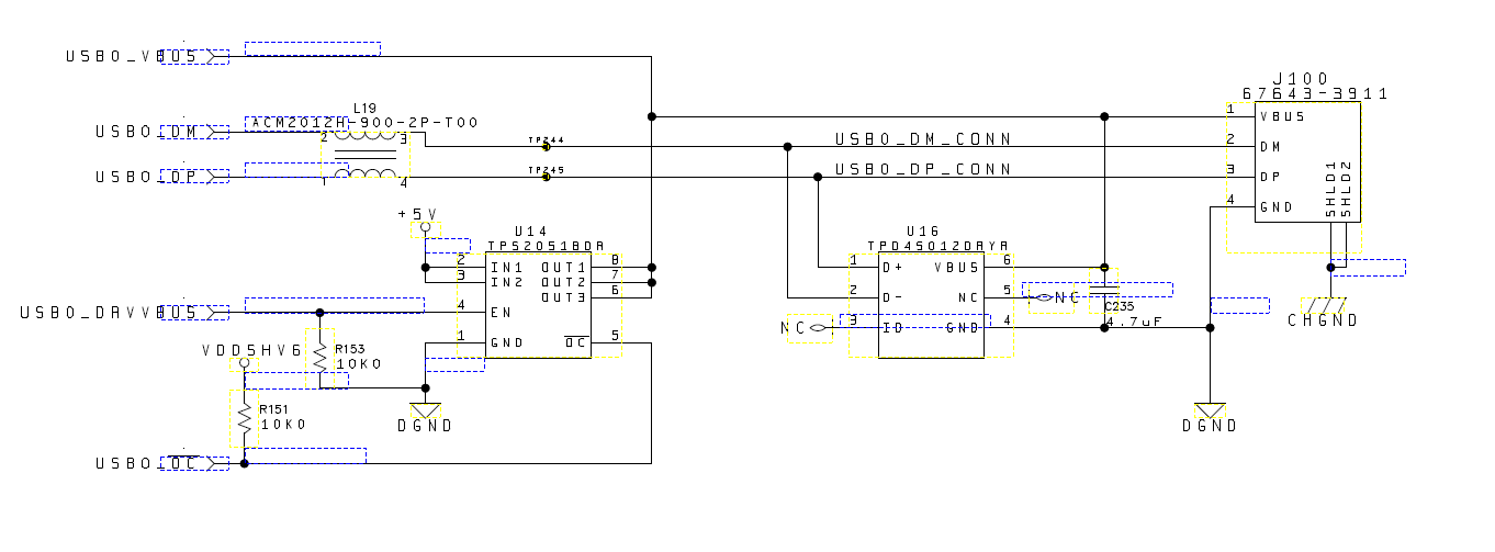
    There is no difference between the ports...they are identical. As to your issue, I wonder if this is a droop issue caused by a lack of sufficient capacitance on VBUS? The USB standard requires =>120uF on Host port VBUS, could you please check yours?

  • DK,

    We don't have 120uF. We only have 4.7uF.

    When my EE tried to replace the capacitor with 180uF, it still does not work. He is putting the cap on the output side of the power switch. 

    Will this be a problem?

  • Please monitor USB0_DRVVBUS and USB0_OC to see if they change during the mode switch.
  • USB0_DRVVBUS is high (3.3V) and USB0_OC goes low when the VBUS drops to 1V, then returns high when VBUS returns to 5V
  • From the TPS2051B Data Manual:

    When the output load exceeds the current-limit threshold or a short is present, the device limits the output current

    to a safe level by switching into a constant-current mode, pulling the overcurrent (OCx) logic output low.

    It appears that either you have a short on VBUS (unlikely), or the device in question is sinking too much current (>500mA).

  • I understand how the current limit operation of the TPS2051B operates.
    The question is why does it sink too much current on USB0 and not on USB1.
    Also, If we configure USB0 and USB1 as HOST instead of ON-THE-GO, I no longer have the overcurrent condition on USB0.
    The circuitry and physical PCB layout are identical for both ports. +5V and GND are being supplied through inner planes so there is plenty of copper feeding each TPS2051B.
  • In your use case the USB host ports are operating as standard root hub ports and must source a VBUS potential of 4.75 – 5.25 volts at 500mA. The voltage on VBUS is required to stay above 4.75 volts as long as the attached peripheral doesn’t attempt to consume more than 500mA of current. The USB specification defines the minimum VBUS capacitance on host port of 120uF and a peripheral is required to have a maximum VBUS capacitance of 10uF. The primary purpose of these capacitor values is to minimize VBUS voltage drop when a USB peripheral is hot plugged to a host port that has power applied.

    Based on the problem description, your voltage drop is occurring long after the peripheral has been attached to the host. So this does not appear to be a hot plug issue. However, your peripheral may be disconnecting and reconnecting the load on VBUS when changing the mode. If so, this would look like a hot plug event and the larger host capacitor must charge the smaller peripheral capacitor. If your product does not use the correct host capacitor or the peripheral capacitor is too large, the charging sharing during a hot plug event my cause the voltage on VBUS to drop below the minimum of 4.75 volts. The same thing may occur if the host capacitor is not located close to the connector or not using a certified cable where excess inductance may allow VBUS to drop below the minimum of 4.75 volts.

    The TPS2051B is designed source up to 900mA before it enters into current limit mode. So if the voltage on the output of the TPS2051B drops below 4.75 volts and the enable input remains high, I can only assume the attached peripheral is drawing more than 900mA or the TPS2051B power supply is not able to source enough current for the peripheral mode change. The host capacitor will supply some current during transients, but it is not expected to supply current in excess of 500mA because a peripheral should never consume more than 500mA even for short durations.

    I do not have any explanation why one port would act different than the other and do not see how the USB controller could be considered if both DRVVBUS signals remain high during the mode change.

    Regards,
    Paul