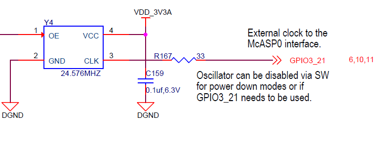
I need help understanding MCLK for my application with the Beaglebone Black (Rev C) because currently I am not seeing any oscillation at GPIO3_21 (P9.25).
In the above diagram, Y4 the oscillator, is connected to GPMC_A11 at PIN 1 (OE) and on GPIO3_21 (mcasp0_ahclk).
I've been trying to determine how these PINS should be defined for proper operation of the oscillator and I'm not getting anywhere.
I am attempting to use mcasp0_ahclk or P9.25 was MCLK for mcasp1 as seen here:
fragment@1 {
		target = <&am33xx_pinmux>;
		__overlay__ {
				mcasp1_pins: mcasp1_pins {
				pinctrl-single,pins = <
					0x1AC 0x00	 	/* mcasp0_ahclkx,  P9_25 */
					0x144 0x24 		/* mcasp1_axr3, P9_16, MODE 4  */
					0x1A8 0x23	    /*mcasp1_axr0, P9_41, MODE 3  */
					0x1A4 0x23  	/*mcasp1_fsx, P9.27, MODE 3 */
					0x1A0 0x23	/*mcasp1_aclkx,P9.42, MODE 3 */
						/* 0x6c  0x07	GPMC_A11  */
				>;
				};
I'm not sure how 0x1ac should be defined as I've seen it defined as an output, 0x00, for the working AudioCape_RevB dts from CircuitCo as well as an input on other discussions. I found that within the main am335x-boneblack.dts mcasp0 has pincltr,single = <0x6c 0x7> as one of the options which the GPMC_A11 pin V17 and 0x7 configures it for GPIO1_27, output. So if both pins attached to the oscillator are setup as outputs then how does this work? If someone can provide some insight/explanations on how to accomplish this task I would greatly appreciate it.
FYI- The codec I am using is a tlv320aic3104, kernel is 4.1-ti-r35.
Thank you,
Bruce


