This thread has been locked.

If you have a related question, please click the "Ask a related question" button in the top right corner. The newly created question will be automatically linked to this question.

C6748 UPP length of DAC data ?

Other Parts Discussed in Thread: OMAP-L138, DAC900

Hi,

I am using the Logic OMAP-L138 EVM board and trying to evaluate the DAC interface.  I have tried the sample

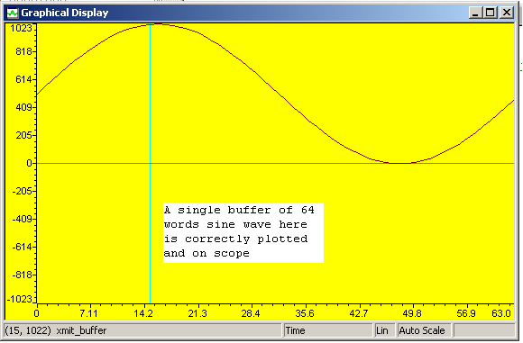
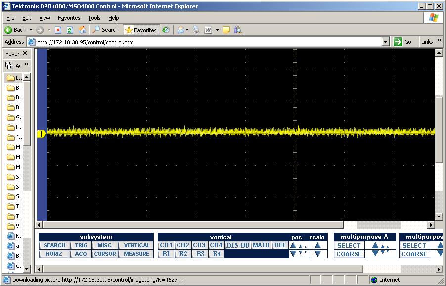
evmc6748_v1\tests\evm\upp and it seems to work fine with a single transfer of 128 bytes and display on my scope a single pulse sine wave.

The descriptor register is set as follows

    UPP->UPQD0 = (uint32_t)&xmit_buffer;//add next DMA transfer
    UPP->UPQD1 = 0x00010080;                        //1 lines 128 bytes per line
    UPP->UPQD2 = 0x00000080;                        //no offset between lines

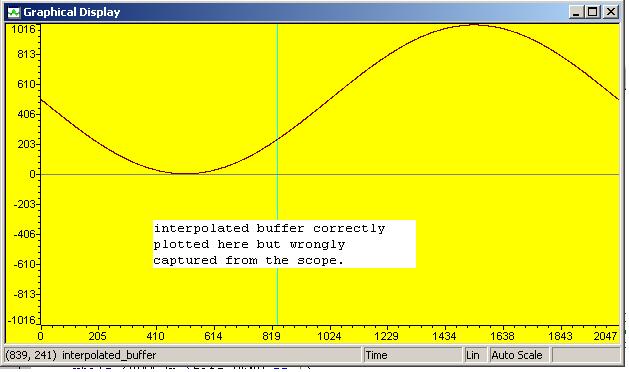
But when I do an interpolation to increase my sampling points to 4096 bytes and changed my descriptor register to

    UPP->UPQD0 = (uint32_t)&interpolated_buffer;//add next DMA transfer
    UPP->UPQD1 = 0x00011000;                        //1 lines 4096 bytes per line
    UPP->UPQD2 = 0x00000080;                        //no offset between lines

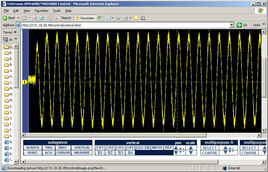
I do not see a sine wave with a lower frequency.  Rather I see a very sharp pulse on both ends ???

Could you tell me what I did wrong with my descriptor setting ?

Thanks,

Kevin

  • kevin nguyen said:

        UPP->UPQD1 = 0x00011000;                        //1 lines 4096 bytes per line
        UPP->UPQD2 = 0x00000080;                        //no offset between lines

    You probably intended to update UPQD2 to the longer line length, but this is probably not your current problem since only one line is being sent.

    What data values are in Interpolated_buffer? You may be seeing the correct response out of the DAC based on the data sent to it. You do not need to copy the whole buffer to the forum.

    But just to make an easy test of your configuration, try copying xmit_buffer to interpolated_buffer several times to fill it and see if you get a longer pulse of multiple sine waves. Then move on to figuring out what is wrong with the rest of the program flow.

  • Hi Randy,

    I intended to draw only one cycle of a sine wave in 4096 bytes in an attempt to have a lower frequency, since the lowest frequency I can go for using the EVM board is 73.24 Khz.  By interpolating the 128 bytes into 4096 bytes or 1/32 I can get a signal close to 2.28 Khz.

    Here is a plot of my xmit_buffer

    And I tried to test your suggestion with 32 copies of my xmit_buffer to see a 32 cycles of my signal and here is the plot

    And I can also see this signal on the scope

    Then I interpolated my sine way from a 64 words to 2048 words sample and here is

    the plot of the buffer before I send it to the UPP using the same function


    But my scope does not display any thing or the DAC does not produce any signal output.  I am at lost right now

    since I do not see any thing wrong with my code yet the DAC works only in high frequency signal.  The DAC being used

    in this EVM board is TI DAC900 and I could not find any thing in the spec that mentions a minimum output frequency.

    Thanks and regards,

    Kevin

  • Kevin,

    This is excellent progress. I always prefer to take very small steps where only one thing changes at a time. This way, you know what changed when things quit working and you know what to look at more closely.

    Your 64-sample case works well, and your 2048-sample case works well when the same sine wave is duplicated 32 times.

    The first scope shot shows the first pulse of the sine wave being a slightly lower magnitude than the rest, but then everything moves larger and the sine waves are the same amplitude.

    Are you using AC coupling with your scope probe? Or is there a high-pass filter you have turned on in the DAC? The CCS graphs show that the first sine wave should be just as high as the others.

    If neither of those questions point to an answer, I would recommend gradually changing the xmit_buffer. For example, with the 2048-sample buffer, zero out all but the first sine wave and confirm that you get the same result as when you used the 64-sample buffer. It should show the same single sine wave output.

    Then interpolate to double the period of the single sine wave and see how the output of the DAC looks. Continue to double the period, filling in those zero'ed terms, until you start to see a change in the scope display that is not following the changes in the xmit_buffer. This will tell you the conditions that lead to the problem you are seeing.

    Please let us know the next results you find.

  • Hi Randy,

    I am using DC coupling on my scope probe and there is no high-pass filter in the DAC or on the EVM output circuit. 

    I follow your recommendation and trace my signal one step at a time by incrementally doubling my interpolation rate.   What I see is rather interesting.  My output signal amplitude attenuates as my frequency goes down when my interpolation rate goes up.  After a few iterations,  at around 9.16 Khz the amplitude of the signal is so small that it would not trigger my scope.  What I found out is that the output signal of my DAC is coupled with a RF transformer and this transformer working frequency bandwidth is between .4 to 800 Mhz.  I guess the designer of this OMAP-L138 EVM board really targets the Mhz signal bandwidth and I am using it for the lower Khz bandwidth.

    Thanks for all of your helpful ideas as I keep doubting myself about my software without looking closely at the circuit.

    Kevin.


  • Which DAC and output and EVM board are you using? My Logic OMAP-L138 EVM is an early board so it might be different, but it has an AIC3106 driving a Line Out connector with a series capacitor and a 20K resistor to ground, so it will also have a cut-off frequency. But I did not find a transformer.

  • I am using the same board that you are using except as a base board.  This board only has the audio/codec interface using the AIC3106 that you talk about.  My DAC interface is on the User Interface board that expands via the video and emif ports.  This UI board gives you additional interfaces such as composite video, s-video, ethernet,48-char LCD panel and A/D and D/A and other goodies.

    http://processors.wiki.ti.com/index.php/GSG:_EVM_Overview_-_OMAP-L138/AM18x

    http://www.logicpd.com/products/development-kits/zoom-omap-l138-evm-development-kit