This thread has been locked.

If you have a related question, please click the "Ask a related question" button in the top right corner. The newly created question will be automatically linked to this question.

AM5728: Problem with OSC0 input clock

Other Parts Discussed in Thread: AM5728

Hi,

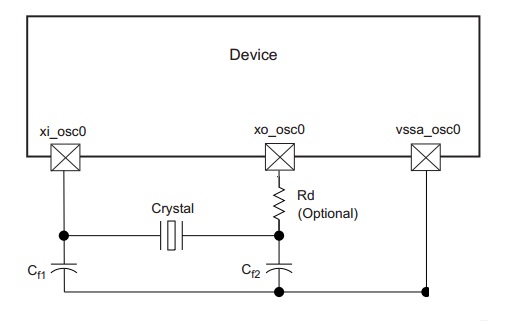
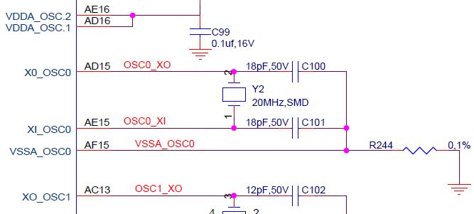
We are facing an issue with system oscillator input clock (SYS_CLKIN1) of AM5728 processor mounted on one of our boards. We have used an external 20MHz crystal  as shown in the below circuit

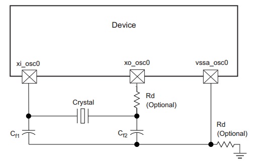
We see that the crystal is not oscillating when the board is powered ON and both the device pins - xi_osc0 & xo_osc0 stay at around 1.8V. As a result the processor is not booting up.

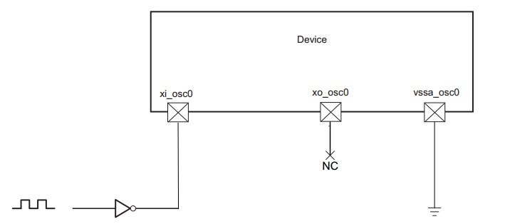
However when we use external 1.8V, 20MHz clock from the signal generator at xi_osc0 pin (as shown in the circuit below), the processor is booting up and working fine. In this case too, the other pin - xo_osc0 is at 1.8V.

Please help us in identifying the root cause for this issue.

Regards,

Elvin

  • Hi Elvin,

    What are your crystal parameters? What are the load capacitors values? Do you have the optional resistors installed? If the crystal is a 4-pin component have you checked that the correct pins are connected? This is a common mistake when designing PCBs.
  • You can refer to Table 6-1 in the AM572X Datasheet Rev. O for OSC0 required values.
  • Hi Biser,

    We are observing this issue only on one board. The other boards where the same crystal circuit and processor is used are working fine with processor booting up.

    We have also tried replacing the crystal and the load capacitors (18pF) with new parts. But still we are seeing this issue.

    FYI,we have used 2-pin, 20MHz crystal with the following parameters

    Frequency Tolerance = +/- 50 PPM
    Equivalent Series Resistance (max) = 50 ohm
    Shunt Capacitance(max) = 7 pF
    Load Capacitance (typ) = 18pF

    We have not used the optional resistor (Rd).

    Regards,
    Elvin
  • These parameters seem OK to me. I will ask the factory team if they have any suggestions. By the way, is VSSA_OSC0 connected to the common GND plane?
  • The load applied to the crystal is the series combination of Cf1 and Cf2, plus the shunt capacitance of the PCB signal traces, plus the shunt capacitance of the AM5728 device.  The formula in Figure 6-3 of the AM572x data sheet shows how the series combination Cf1 and Cf2 contributes to crystal loading. So you should not be using 18pF capacitors for Cf1 and Cf2 if the crystal was cut for 18pF of loading.

    Normally the combined shunt capacitance of the PCB and AM5728 device will be 2-3pF, so the series combination of Cf1 and Cf2 would need to be about 15-16pF for a 18pF crystal.  This would require Cf1 and Cf2 to be 30-32pf, which is greater than the value defined in the AM572x data sheet.

    I recommend using a crystal that has been cut for a load capacitance of 10-12pF.  If you used a 10pF crystal and the combined shunt capacitance of the PCB and AM5728 device is 2pF, you would need to use 16pf capacitors for Cf1 and Cf2.

    The wrong loading may not be the reason the oscillator doesn’t start.  Were you able to see the oscillator output signal changing when using the external signal generator to source the input?  This problem could be explained if the bad board has an open on the oscillator output signal.

    If the oscillator does not start after verifying output signal looks okay and you replace the crystal and capacitor values such that the crystal circuit meets the requirements defined in the data sheet, add a 1M ohm resistor from the output to the input to see if this helps.

    Regards,
    Paul

  • I update my previous post to correct a typographical error and posted this reply so you get another email notice.

    Regards,
    Paul
  • Hi Biser,

    We have used the below circuit for the crystal oscillator where VSSA_OSC0 is not connected to the board ground.

    Hi Paul,

    To clarify again, we are observing this issue only on one board. The other boards where the same crystal circuit and processor are used work fine.

    The oscillator output pin - xo_osc0 is at 0V when the board is OFF. On powering ON the board with the signal generator connected (at the oscillator input), the voltage at xo_osc0 rises to around 1.8V . We are not observing any toggling on this pin.

    Regards,

    Elvin

  • VSSA_OSC0 should be connected to common GND. Also please see Paul's comments about the load capacitors. I missed this in my previous reply.
  • Hi,

    Below is the snip from EVM schematics.

    from the EVM BOM the crystal part is ABM7‐20.000MHZ‐D2Y‐T; which has 18pF load capacitance.

    cf1 and cf2 from the schematics is 18pF.

    Any comments?

    Regards,

    Srinivas J

  • The AM572x GP EVM was designed for TI by a contract engineering firm. We were not aware they used the wrong value load capacitors for the selected crystal until the board was in production. This is unlikely to cause a functional issue, but may pull frequency of oscillation a few PPM from the expected frequency of oscillation.

    As you can see in a previous reply to this thread, I recommend using a crystal that has been cut for a load capacitance of 10-12pF. Please read my post on Jan 6, 2016 for more details related to selecting the proper crystal circuit components.

    Regards,
    Paul

  • Dear Paul,

    In the AM572x IDK, a different circuit is used for OSC0 as compared to the GPEVM. The load capacitance of the crystal is 18pF and 24pF capacitors are used. Also, additionally, the optional 0 ohm resistor at the XO_OSC0 pin is mounted and a 1Mohm resistor is used in parallel with the crystal.
    Please let me know why the circuit is different in IDK and GPEVM. Also, which one is recommended?

    Regards,
    Prachi
  • The series combination of two 24pF capacitors is 12pf. So I assume the IDK designer felt like his PCB has about 4pf of shunt capacitance.

    The 1M parallel resistor is typically used to help kick-start oscillation of the crystal circuit. Our oscillators normally have an internal resistor for this purpose, but maybe the IDK designer wanted to provide an external option in case the internal resistors wasn't enough to kick-start his crystal circuit.

    The optional 0 ohm resistor is a place holder in case a series resistor needs to added to reduce the crystal circuit drive power.

    Regards,
    Paul 

  • Hi Elvin, Srinivas,

    Were you able to identify the root cause for this? Was it EOS? I'm trying to see if it's similar to the following issue we are trying to solve: e2e.ti.com/.../2266376

    Thanks,
    Antonio