This thread has been locked.

If you have a related question, please click the "Ask a related question" button in the top right corner. The newly created question will be automatically linked to this question.

OMAP LCDK starterware examples on vga

Hello there!

I have the L138 LCDK board. I want to capture video data from a CMOS image sensor and store it to SD card. I was hoping to understand the code by looking at the vpif_loopback demo. But i saw that the name suggests it displays on LCD. Is it the same as the VGA port ? if not what can be done to port it to vga. I tried running the demos "game/demo/vpif_loopback". None of these 3 shows anything on my VGA

Thanks in advance

Vivek

  • HI Vivek,

    Yes, your understanding is right.It will display on the LCD monitor which connected to the VGA port.

    In addition to the VPIF example, 

    In the below link, the video training is available for Face detect demo project in which they demonstrate detecting faces using a composite camera to capture and display the image through VGA.  

    This demonstartions comes with the C6748 BIOS C6 Software development Kit (  C6BIOS SDK )  with the source code of the projects.

  • Dear Vivek,

    I have the L138 LCDK board. I want to capture video data from a CMOS image sensor and store it to SD card. I was hoping to understand the code by looking at the vpif_loopback demo. But i saw that the name suggests it displays on LCD. Is it the same as the VGA port ? if not what can be done to port it to vga. I tried running the demos "game/demo/vpif_loopback". None of these 3 shows anything on my VGA

    In VPIF loopback code, you have to provide the video input into Composite input and you will get the video output on VGA port.

    The same HW setup is required for facedetect code which Shanakri was suggested.
  • Thanks for replying Shankari

    I went to the link above only to find that the videos aren't there anymore.
  • Titus,

    I have a CMOS analog camera connected to Composite port and my VGA monitor connected to VGA port. But when I Debug the code on CCS, nothing shows up on my VGA. The monitor even says its not detecting a signal. What could be the problem? I havent changed anything in the code. I just loaded the code and setup my debug configuration to match the L138 LCDK.( Also I had to set the switches for NAND boot mode because in UART boot mode my CCS kept saying that the board was in Reset mode). .
  • Also I just noticed that whenever I debug the c674x with the vpif code, the GPIO led starts blinking (because the last code I debugged on the ARM was GPIO ???)
  • Yes, that could be the problem.
    Please keep boot mode to UART to make sure that no program is running on any cores DSP/ARM.

    It should work if you didn't change the code.
    I have also used DVD player output for connecting to composite i/p of LCDK.
  • Titus,

    So I tried playing with the code a little to suit my camera, but the display still doesnt show anything. And this is after I commented out the regVal check in the vpifcompositeInit function, where it was in an infinite loop because the regVal was  always 0x11. After commenting that, the display would switch ON, but nothing. While I was changing the code, at one point it even displayed the "The current timing is not supported by the monitor display. Please change your input timing".

    Here are the details about the camera I am currently using:
    http://www.amazon.com/ePathChina%C2%AE-Smallest-Pinhole-Support-Standard/dp/B00IEXTOMA/ref=cm_cr_pr_product_top?ie=UTF8 


    Image Sensor: 1 / 4" CMOS
    Resolution: 1280 x 960
    Pixel: 5 Mega Pixel
    Horizontal Resolution: 600TVL
    Minimum Illumination: 0.5 Lux
    S / N Ration: > 48db
    Gama Characteristic: 0.45
    Refresh Rate: 60 f / s
    Electronic Shutter: 1 / 60' 1 / 100,000s
    Operating Temperature: - 40 ~ + 85 Centigrade
    Power: DC12V 1A/2A
    White Balance: Auto
    Audio Output: Single Track
    Video Output: 1vp - p 75 Ω; Negative
    Synchronizing System: Interior Synchronization
    Image Color: Colorful
    Color: Black
    Item Dimensions: 12 x 12 x 8 mm
    Package Dimensions: 68 x 58 x 45 mm
    Package Weight: 33g  

    In my knowledge only the capture_widht/height and Display width/height values need to be changed depending on the camera right ?! I tried changing them to vga values. That didnt help. What do you think. pls help.

    Thanks

    Vivek

  • Thats it, I am creating a new thread for this.

  • Can you provide the link for your new post ?
    Have you tried to connect this camera to your TV and able to see the camera streaming o/p on your TV display ?
  • I didnot create a new thread. I was able to get the code working when I change the resolutions to the following:

    Capture Height : 525

    Capture Width: 720

    Display Height: 480

    Display width: 640

    For the above values I got the video on the the VGA, but there was 2 issues I noted:

    First of all,

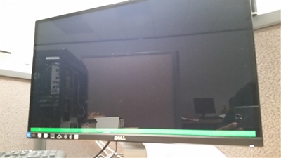
    1. There was a green bar about 20 lines high near the bottom of the screen.


    In the above picture, I've disconnected the Camera. Even then the green bar was still there. Why is this green bar there and how can it be removed?

    It was then that I tried changing the resolution. Thats when the next issue came up.

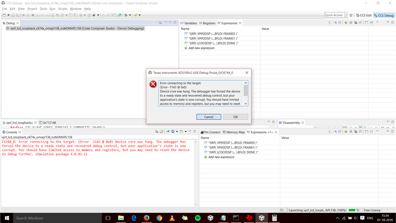
    2. When i tried to change the resolution and debug the code, it would give a black screen on output. However, the next time I debugged, it showed an error as you can see in the below pic.

    If I press okay, it would go forward with the debugging, loading the program. But again black screen. Nothing not even the green bar shows up on the monitor. After this the board behaves the same way to any code change unless I reset the board and plug out and plug in the cables once. What could be the issue.

    Vivek


  • It was then that I tried changing the resolution. Thats when the next issue came up.

    2. When i tried to change the resolution and debug the code, it would give a black screen on output. However, the next time I debugged, it showed an error as you can see in the below pic.

    If I press okay, it would go forward with the debugging, loading the program. But again black screen. Nothing not even the green bar shows up on the monitor. After this the board behaves the same way to any code change unless I reset the board and plug out and plug in the cables once. What could be the issue.


    For second time debugging (continuous debugging) , please POWER OFF and POWER ON or RESET the board to get the expected behavior.