This thread has been locked.

If you have a related question, please click the "Ask a related question" button in the top right corner. The newly created question will be automatically linked to this question.

Can AM437x support 3x EnDat with Ethercat slave device?

Expert 2355 points
Other Parts Discussed in Thread: SYSBIOS, DRV8313, DRV8313EVM

Hi,
It's being considered whether AM437x is used as Ethercat slave device and 3pcs motro contorl.

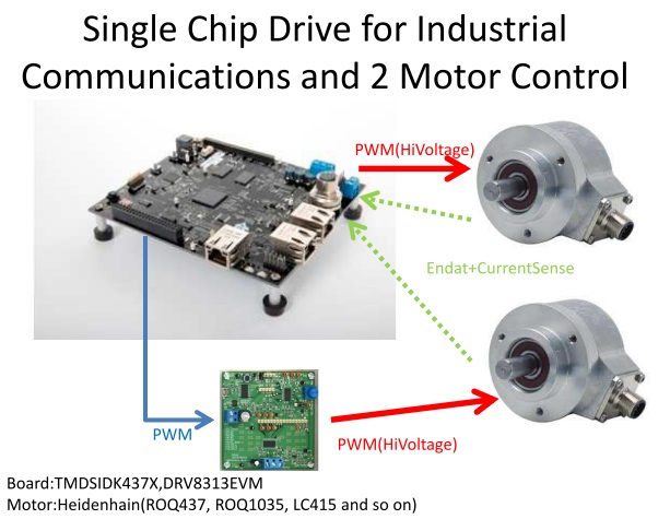
In our case, we plan to use 3-phase BLDC motor with endat.

The one ICSS is used to EtherCat alve device and the other one is used 3x motor sequence with endat.

so, can AM437x cotrolled 3pcs endat motor?

It seems that the ISDK is supported up-to 3 encoders with identical part number.
What does it mean indentical number?(1GHz-device?)

SYSBIOS Industrial SDK 02.01.01 Release Notes

New In This Release:EnDat master concurrent multichannel support (up-to 3 encoders with identical part number @ 8MHz)

processors.wiki.ti.com/.../SYSBIOS_Industrial_SDK_02.01.01_Release_Notes

best regards,
kyt

  • Hi,

    I will forward this to the Industrial team.
  • Hi,

    It refers to ID number that uniquely identifies a particular type of encoder, eg. ROQ437, ROQ1035, LC415 and so on. So if ROQ437 is used in multi channel configuration, all encoders should be ROQ437 (can be 1, 2 or 3)

    Regards
    afzal
  • afzal-san

    Thank you for your reply.
    I understand.

    bestregards,

    kyt
  • Biser-san

    In case of controlling 3phase-BLDC, the 3system PWM module are occupied to one motor.
    Therefore the number of the motor which can be controlled will be 2 because AM437x supports up to Six PWM(A/B).

    Is it correct understanding?

    datasheet:
    www.tij.co.jp/.../am4379.pdf
    Up to Six Enhanced High-Resolution PWM Modules (eHRPWMs)

    best regards,

    kyt
  • Hi afzal-san,

    AM437x ICSS seems to have three signal sets of EnDat data transfer in Table 30-21 on TRM (SPRUHL7D). The one signal set consists of ENDATn_IN, ENDATn_CLK, ENDATn_OUT and ENDATn_OUT_EN, then n is 0, 1 or 2.

    For multi channel configuration, each of encoders, e.g. three ROQ437 encoders is connected to the one signal set of EnDat via RS-485 transceivers that consists of two drivers and one receiver.

    Is my understanding correct?

    Best regards,

    Daisuke

  • Hi Kyt-san,

    In the 2.1.1.2 SYSBIOS Industrial SDK, only 1 out of the 2 PWM outputs is made to function as PWM (complementary lower & upper leg transistor gates) in the 3 PWM instances, other PWM output is available. So it should be possible to control 4 motors as per this scheme considering the other 3 PWM instances, though it has not yet been attempted.

    Also refer AM437x IDK schematics & DRV8313 datasheet.

    Regards

    afzal

  • Hi Daisuke-san,

    not sure i understood your question correctly, each channel ENDAT pins has to be connected to RS-485 transceivers, one each for clock & data.  One for data should be able to transfer both ways.

    AM437x IDK uses on board transceivers for channel 0, refer it's schematic. Similarly transceivers has to be connected for other 2 channels.

    Also refer TI Design for interfacing EnDat, it works with AM437x IDK for channel 1 & 2.

    Regards

    afzal

  • afzal-san

    Thank you for reply.

    It seems that the AM437x can contorl 2 motors with DRV8313 and Endat.

    The evaluation environment is assumed by simple composition.

    Partial improvement is needed, but is there a better way about composition?

    (0ohm jumper resistor remove,ICSS connection and so on)

    best regards,

    kyt

  • Hi Kyt-san,

    1. If BLDC motor has to be run, relevant motor control algorithm has to be adapted for AM437x. FOC algorithm in IASDK is for PMSM (PM machine that would would give sine wave if run as generator, but for BLDC it would be trapezoidal)
    2. As only one onboard EnDat connector is available on AM437x IDK, external transceiver circuitry would be required to connect the second encoder (refer EnDat TI Design mentioned earlier in this thread) - this can connected via expansion connector J16 (refer schematics)
    3. DRV8313EVM require 3 PWM signals & 3 control signals - these can be taken out from expansion connector J16
    4. As it is BLDC, seems only one current sense per motor-drive set would be sufficient. And in the current implementation, 2 phase current is being monitored, 1 out of these ADC input signal instead can be connected to DRV8313EVM for current sense via expansion connector J1, so that current sense on both motor-drive set can be achieved with minimal changes.

    Regards
    afzal