This thread has been locked.

If you have a related question, please click the "Ask a related question" button in the top right corner. The newly created question will be automatically linked to this question.

Double buffered EDMA transfer for Left/Right McASP data


I have pingPong buffer working with EDMA. But I would like double buffered system for two sepate L/R channels of Stereo audio data.

For Transmit, Links are connected as follows:

EDMA PaRAM set 1 -> PaRAM set 64 -> PaRAM set 65 -> PaRAM set 64 -> ...... for PING_OUT, PONG_OUT buffers

For receive, Links are connected as follows:

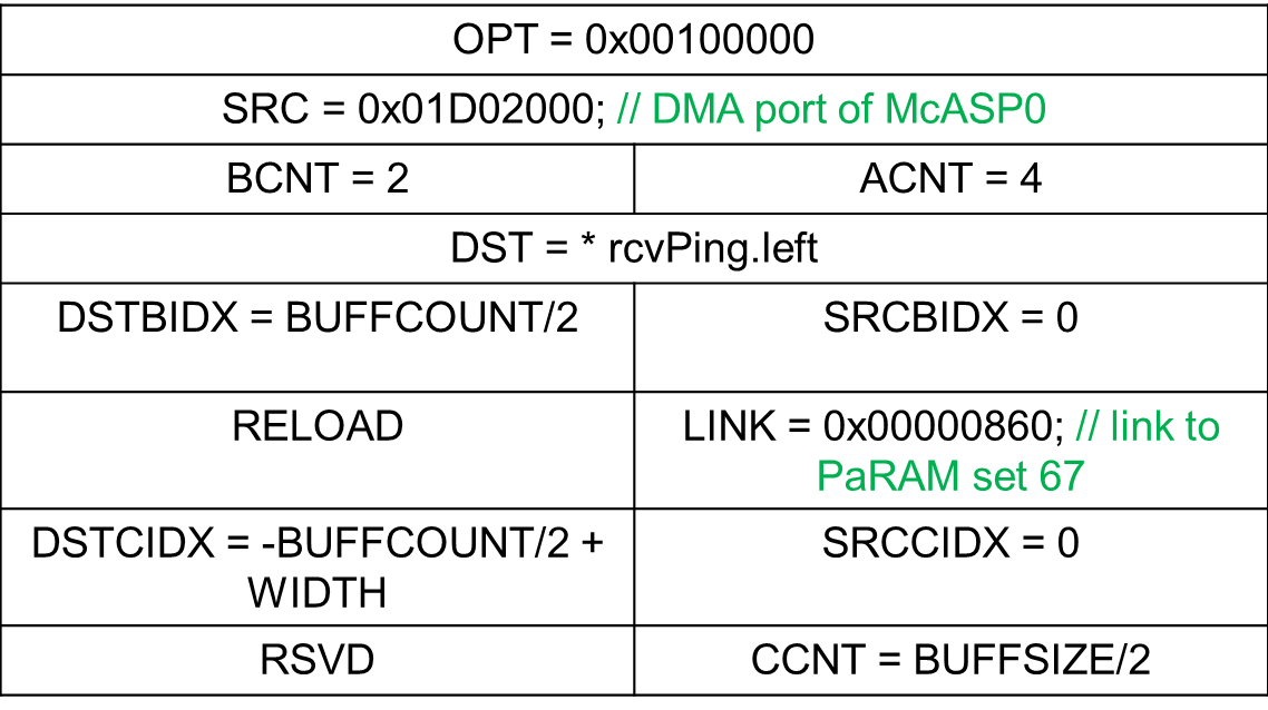
EDMA PaRAM set 0-> PaRAM set 67 -> PaRAM set 68 -> PaRAM set 67 -> ...... for PING_IN,PONG_IN buffers

However, i will have long buffers of 4096 values each channel for Left and Right and the TI C6748 (LCDKC6748) seems to run out of memory for it. Without Optimisation! Nevertheless, i would like to have separate In/Out buffers for left and Right channel audio data. That way, i will not have to sort the incoming McASP data stream explicitly in my ISR or SWI or Task.

RcvPingL , RcvPong L

RcvPingR , RcvPong R
Similarly separate buffer for left/right channel for transmitting it.

XmtPing L, XmtPong L
XmtPing R, XmtPong R
Coudl you please guide how should PaRAM links be created?

  • Sherry,

    Please see the EDMA3 User Guide and look at the Data Sorting Example that is included in section 3. Once your ping or pong buffer has filled with the interleaved L/R samples, you can then use the Data Sorting technique to split the data into separate L and R buffers are you are trying to do.

    Regards,
    RandyP

  • Thank you for a giving a great head start. Looking at section 3.3, it seems that for my application it should be reduced to the following diagram

    Now, in the example of Data sorting, Destination address is shown as 1180 0000h on Page 62 of sprugp9b.pdf. If I have Left and Right buffer each of size 4096.( each element is 32 bit and an array of 4096 elements).
    Then my Left channel buffer is located in address 1180 0000h. Should my right buffer be starting at 1180 4000h ???
    Rephrasing my question as, Are the memory addresses in this diagram ascending horizontally?
    If not, then I think this sorting is orthogonal to what I need.

  • Is it possible to skip interleaved buffer altogether and just set pointers such that data is directly written down in sorted form. I want to minimise memory use.
  • Sherry,

    The I2S samples comprise two 16-bit samples in a single 32-bit word. So it has to be read as both samples in one access.

    You definitely want to read it as a single 32-bit word for EDMA3 peripheral-access efficiency. Not doing so has led many systems to have throughput issues.

    Get it working with the straight-forward method you are looking at right now. Reduce the buffer sizes so you can fit them all in, or move them to external memory for testing purposes and to get it working. I recommend reducing the buffer sizes, and then you can make some optimizations after that.

    When you have it working, please post your PARAM settings to this thread and explain what you would then like it to do differently.

    Regards,
    RandyP
  • This is what my buffer definitions are like

    #define BUFFSIZE 256		//Left and Right buffer size = BUFFSIZE/2
    #define BUFFCOUNT	BUFFSIZE*4
    #define DATA_SIZE (BUFFSIZE/2)
    typedef struct rcv_data_buffer
    {
    	int32_t left[DATA_SIZE]; 
    	int32_t right[DATA_SIZE]; //right buffer will be adjacent to left buffer in the memory location
    } RCV_DATA_BUFFER;
    
    
    typedef struct xmt_data_buffer
    {
    	int32_t pingL[DATA_SIZE]; //pointer will be used to point to this location
    	int32_t pingR[DATA_SIZE]; //right ping will be adjacent to left ping
    	int32_t pongL[DATA_SIZE]; //another pointer will be used to point to this location
    	int32_t pongR[DATA_SIZE]; //right pong will be adjacent to left pong
    
    } XMT_DATA_BUFFER;


    This is how I picture the memory space JUST for receive buffer for ping (in pingPong)

    My parameters for receiving the I2S data stream (32 bit) are defined in paRAM set as follows:
    ACNT = 4 (4 bytes, 32 bit words)

    BCNT = 2 (number of channels)

    CCNT= BUFFSIZE/2 (number of frames received)

    The source is MCASP sending 32-bit words. These words are read from the same location, hence SRCBIDX = SRCCIDX = 0.
    Destination is my received buffer array where I want the data to be written (and sorted simultaneously). The first half of buffer has to be left channel data and second half is right channel data.
    Hence in the struct definition above, L/R are defined next to each other so they occupy memory space just after one another. Now, the SRCBIDX has been defined such that, after writing first Left channel sample (L0), the B-index jumps to later half of the buffer array and writes first right channel sample (R0). After writing R0, the first frame is completed. So the DSTCIDX has a negative value, jumping back to upper half of the buffer array and +4 so that it writes a new frame L1, without overwriting L0. 
    Please correct me if this concept won't work.

  • Sherry,

    What value do you use for RELOAD?

    What do you get when you try your concept?

    Regards,
    RandyP
  • Hello,

    I am back to working on this now. 

    Reload field is 000

  • The output was a stunned silence. zero output. Input is sinosoid that works fine if I do not try data sorting ( so I know I have a code to get back to and test)
  • If a negative value for Destination C Index is required, for example, if:
    BUFFCOUNT = 512,
    WIDTH = 4.
    Then according to the picture above for DSTCIDX, my result should be negative number and 2's complement of -252.
    Is that correct?
    I am getting the following warning for DSTCIDX:
    #69-D integer conversion resulted in a change of sign

  • Sherry,

    Since you are using A-sync, RELOAD=0 is wrong. Are you using A-sync in the non-data-sorting version and RELOAD=0 works?

    If you are getting a C compiler or linker warning message, then your code is written incorrectly. Check your variable and field types and your type-casting.

    In the debugger, you should be able to see the PARAM updating. Is it updating naturally the way you expect it to do or is it not?

    Also in the debugger, you should be able to watch your data buffers being filled. They will likely look like random data, but if your sound is sufficiently low frequency compared to your sample rate, you should be able to make out the sine wave. It might be helpful to set a breakpoint somewhere in the code, like in an ISR from when all buffers have been filled. You may have to restart after hitting the breakpoint to run it again, but you can observe the input buffers under different conditions and see what is happening with the data.

    Regards,
    RandyP