This thread has been locked.

If you have a related question, please click the "Ask a related question" button in the top right corner. The newly created question will be automatically linked to this question.

6638K2k SPI boot problem (continued 3rd)

TI experts,


I post a question and there is not any further reply, so I post another one. and another one. and ...

(1)The major problem is how to build the .bin file and where is the utilities for 6638? Such as romparse and hex6x and etc. Especially the romparse, an invoke guide(how to configure the .map file for 6638) is also essential, because the parameter table structure is different from keystone I,such as 6670.

(2)In the bootloader example, there is only .dat file, but there is not any building precedure scriptes demonstrated, however ,the scripts example is most helpful.

such as 6670 example below:

----------------------------------------------------

FILE NAME: runscript.bat

DETAILS:

..\utilities\hex6x -order L ..\utilities\boot_script.rmd bootcode.out

..\utilities\b2i2c boot_code.btbl boot_code.btbl.i2c

..\utilities\b2ccs boot_code.btbl.i2c boot_code.btbl.i2c.ccs

..\utilities\romparse ..\utilities\spi.map --------->(details as below, in case parameter structure is different ,the romparse shoule update,where?)

ren i2crom.ccs spirom.ccs

copy spirom.ccs spirom_le.dat

echo generate the dat file from spirom_dat.ccs

..\utilities\byteswapccs spirom.ccs spirom_le.swap.dat

echo generate 2 bin files from spirom.ccs

..\utilities\ccs2bin   spirom.ccs     spirom_le.bin

..\utilities\ccs2bin -swap spirom.ccs spirom_le.swap.bin

-------------------------------------------------------------------------------------

The last post is here: 

Looking forward to your reply.

The 6638 SPI boot still not work, and there is no way to debug. Can you tell me how to debug and confirm where the problem is.

  • Hi Frank,

    Apologize for the delay, We have ARM based SPI boot examples and utilities for Keystone II devices from below link,

    http://processors.wiki.ti.com/index.php/KeystoneII_Boot_Examples

    Git repository to download  boot exmaples,

    https://git.ti.com/keystone2_boot_examples

    I am working with factory on this request. Thank you for your patience.

  • Raja,

    1. Can you please merge this post to my last one? All the background is in my last post.

    Rahul had already provided the above example link and I had downloaded and studied.

    I have new questions and need help. I want you to reply to my question so I post this post, but I prefer you merge my post together because the question in the  last thread is still not answered and closed.

    By the way,are you sure the SPI boot example is for ARM master boot mode? But I need CorePac master mode now!

    2.Can you give an example?

     I am afraid the https://git.ti.com/keystone2_boot_examples is helpless. I still have no idea how to convert my .out file to the correct .bin file and how to debug.

    The example I want is similar to the one attached to this below answered thread, can you provide me the similar example for 6638? HOW TO BUILD THE BIN FILE is most important and helpful ! However, I need Corepac master example but not ARM mastered.

    Thank you!

  • Hi Frank,

    Keystone II are primarily ARM boot master devices so all the examples that we have created so far are ARM boot master examples but the DSP boot master should also work the same way as Keystone I device. 

    I will try to create a quick example for you to boot from SPI with DSP boot master and send you the instructions. In the meantime, I am attaching the romparse version that we have been using for keystone II device so that your progress is not blocked by this.

    romparse.zip

    The hex6x utility is still part of the C6000 compiler which gets installed with Code composer studio environment. You can locate the utility under 

    C:\ti\ccsv6\tools\compiler\c6000_7.4.14\bin

    All other ccs2bin, b2ccs utilities are same as Keystone I devices and are also part for the Keystone II ARM boot examples.

    The sequence to build the boot image is the same as in Keystone I devices. after building your out file 

    hex6x -a -boot -bootorg 0x400 -romwidth 32 -memwidth 32 app.out -o btbl.b
    b2ccs btbl.b testsmall_gem.btbl.ccs

    romparse -nTables 1 spirom.map

    I have also attached the spirom.map file that you can use.

    https://e2e.ti.com/cfs-file/__key/communityserver-discussions-components-files/791/spirom.map

    Hope this helps.

    Regards,

    Rahul

  • Hi Rahul,

    Thanks a lot for your help!

    1.Since I have no expirence on MinGW, I have to study a lot before I can build the Romparse.exe. Can you build a Romparse.exe and  send a SPI boot example to me? (Romparse.exe is provided  for 6670 in mcsdk.)

    2.By the meantime ,I have another question need your help. About DDR boot configure on 6638.

    Look, for 6638 DDR configuration during boot, is it the same  with 6670?? If so, a ddr configuration example would be highly appreciated!

    3. I have studied the documents about DSP bootloader. The boot loader user guide tells we should use boot configure table to config the DDR,and show the detail boot config table format  again and again. BUT, we just use a DATA_SECTION to config the ddr. There is NOTHING to do with boot configuration table so far!

    So, can you please tell me,if I want to use the boot configuration table (a series of Entry Addr,Set mask,Clear mask...). How to use, how to append the boot configuration table to my boot image(.bin file).If I can config the Register use boot configuration table, I can confiure all the DDR registers,and no need to have a second stage to configure the specifies registers.Like you demonstrate below.

    We have demonstrated how to convert boot table and append parameter table many times, but there is not a word about boot configuration table. I am very confused on how to structure and append a boot configuration , is there any utility similar like romparse? Is there anyone had successfully append a boot configuration table to a image so far? (not a DATA_SECTION).

    Thank you!

    Best Regards,

    Frank

  • Hi Frank,

    I have quickly put together an DSP SPI boot example for you to try on the K2HK device. This example doesn`t configure the DDR but will demonstrate how to create the boot image and how to use romparse. I have not tested this on an EVM but this example has been tested on our custom hardware used to bring up new silicon. You can modify the boot parameter table as per your application requirements.

    Boot_K2H_SPI.zip

    TO rebuild the example, set the ARM and DSP compiler path in the .sh or .bat file and run make all in spiboot_test folder. The folder contains all the utilities required to build a SPI boot image in boot table format.

    To answer you second set of questions. The DDR configuration table for K2H, is described in section 8.1.2.4.10 K2H data sheet here:


    The structure for DDR configuration table is also defined in the tiboot.h file that we have provided in the Keystone II boot examples


    Please let me know if you run into any issues.

    Regards,

    Rahul

  • Rahul,

    Thanks for your example!

    But there are still some confused questions. It is majorly about the Romparse.exe.

    I have read the source code of Romparse, too.

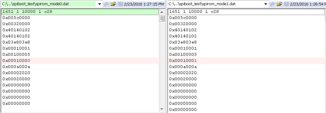
    Q1.  In spirom.map file, I changed value  " mode = 0" to "mode =1", the result .ccs file after romparsed is still 00 00; it doesn't make sense,can you have a try?

    Q2.  In spirom.map file, I add value  "dev_addr_ext = 0x400;" the result .ccs file after romparsed is still 0x2020; can you have a try? Why?

    Q3.  I study the romparse.h and found the below nonsense defination and code:

    ------------------------------------------------

    /* Define the number of boot parameter tables that will be put on the rom */

    #define NUM_BOOT_PARAM_TABLES       64

    /* Define the size reserved for the PCI configuration table */

    #define PCI_EEAI_PARAM_SIZE    0x20

    /*************************************************************************************

    * Definition: fixed i2c map locations

    *************************************************************************************/

    #define PCI_PARAM_BASE  (NUM_BOOT_PARAM_TABLES * 0x80)

    #define DATA_BASE       (PCI_PARAM_BASE + PCI_EEAI_PARAM_SIZE)

    ...

    if (secureBoot == TRUE)
    romBase = DATA_BASE_SECURE;
    else
    romBase = (num_boot_param_tables * 0x80) + (pciTable * PCI_EEAI_PARAM_SIZE);

    ...

    so

    romBase   = 64*0x80+0x 20 = 0x2020!! You are the bug!

    --------------------------------------------------

    BUT!

    In the 6638K2K datasheet, the DEVSTAT Boot Mode Pins ROM Mapping (Figure 8-1) demonstrates that there  should only 8 parameter tables,why " #define NUM_BOOT_PARAM_TABLES       64" ? This nonsense defination wasted a lot of image space.

    and, Romparse is specified for I2C or SPI boot, why there have PCI parameter table? 

    Q4. Small question,  

    case BOOT_MODE_SPI: current_table.common.length = sizeof(BOOT_PARAMS_SPI_T); 

    From Tiboot.h in Keystone 2 Boot example your provided, the spi parameter table size should be 46 byes, or 0x2E in Hex format. But unfortunately, it is 0x5C in the .ccs file after romparsed. Why 0x5C?

    I found there maybe a lot of bugs...

    Thanks for your help!

    Regards,

    Frank

  • Hi Frank,

    Thanks for reviewing the utility and the output of the utility.  Here are my response to your questions.

    Frank Deng said:
    Q1.  In spirom.map file, I changed value  " mode = 0" to "mode =1", the result .ccs file after romparsed is still 00 00; it doesn't make sense,can you have a try?

    I tried this at my end and I do see the mode value change. Here is the snapshot from the diff:

    Frank Deng said:
     In spirom.map file, I add value  "dev_addr_ext = 0x400;" the result .ccs file after romparsed is still 0x2020; can you have a try? Why?

    I get an "unrecognized SPI configuration (token = 273, value = 1024, line 33)" when I add that configuration to my map file so I assume the tool ignores that setting. Are you seeing the same error. With SPI boot mode only the following parameters have any effect in the map file.

    • OPTIONS
    • ADDR_WIDTH
    • N_PINS
    • CSEL
    • MODE
    • C2T_DELAY
    • BUS_FREQ_100KHZ
    • NEXT_DEV_ADDR
    • NEXT_CSEL
    • DEV_ADDR (This is auto populated using addExeFile function to progFile[i].addressBytes = romBase )

    Frank Deng said:

    romBase   = 64*0x80+0x 20 = 0x2020!! You are the bug!

    --------------------------------------------------

    BUT!

    In the 6638K2K datasheet, the DEVSTAT Boot Mode Pins ROM Mapping (Figure 8-1) demonstrates that there  should only 8 parameter tables,why " #define NUM_BOOT_PARAM_TABLES       64" ? This nonsense defination wasted a lot of image space.

    and, Romparse is specified for I2C or SPI boot, why there have PCI parameter table? 

    romBase is a customizable field that you need to set based on your boot requirement. This seems to be setup in romparse to load the image from a large offset and the offset seems to be inserted using the size of the boot parameter field. If you don`t want to place your image at such a large offset you can limit the number of boot parameter tables to be 8 and remove the offset of the PCIE configuration table. On some Keystone II devices we have the option for users to pass a PCIE parametter table so that the Serdes and PCIE is initialized and ready to send or receive data by the time application boots. you can change the NUM_BOOT_PARAM_TABLES and remove the PCIE configuration table offset ( (pciTable * PCI_EEAI_PARAM_SIZE)) to compute the romBase you want to insert in your image.

    Frank Deng said:

    Q4. Small question,  

    case BOOT_MODE_SPI: current_table.common.length = sizeof(BOOT_PARAMS_SPI_T); 

    From Tiboot.h in Keystone 2 Boot example your provided, the spi parameter table size should be 46 byes, or 0x2E in Hex format. But unfortunately, it is 0x5C in the .ccs file after romparsed. Why 0x5C?

    This seems to be a bug in the types.h file. It defines UINT16 as follows

    typedef unsigned int UINT16

    This needs to be changed to 

    typedef unsigned short UINT16

    Also change the typedef for BOOL in romparse.h to typedef short BOOL instead of int. This will cause the boot master field in boot parameter table to be detected as 32 bit field instead of 16 bit. You will need to rebuild the utility for this to take effect.

    Regards,

    Rahul

    PS: Updated ROM parse is provided here:

    5327.romparse.zip

  • Hi Rahul,

    Thank you so much for your help and patience!

    Sadly, I found more bugs about romparse.

    1. When the exefile (.i2c.ccs) to be romparsed is small size,like 10KB, everything goes normal. The CSEL can be set to 0.

     When the exefile is large size like 20MB, there have warnings: when I go to the source code it says:

    ----------------

    case CSEL: if ((value != 2) && (value != 1))
    fprintf (stderr, "Warning: Invalid csel value specified (%d) for SPI (line %d)\n", value, cline);
    current_table.spi.csel = value;
    break;

    case NEXT_CSEL: if ((value != 2) && (value != 1))
    fprintf (stderr, "Warning: Invalid next csel value specified (%d) for SPI (line %d)\n", value, cline);
    current_table.spi.next_csel = value;
    break;

    ----------------

    Nonsense!

    Q1:  CSEL: Please check parameter table in the 6638K2K datasheet, the csel should be 0-3!!  When I set the "csel = 1" to avoid this warning, sadly, it can not boot.

    Q2: CRITICAL issue: When the input .ccs file to romparse is large file(20MB),and I change the csel value to avoid all warnings, Fatal error still exsits, said "the memory  can not be read“ and etc and the i2crom.ccs can not be generated. But for small .ccs file, no warning and i2crom.ccs file can be normally build.Can you try big file?.

    So, is there any procedure difference and limitation for small and big size when use romparse?

    If so, please change the size limitation to as big as possilble and send me the romparse.exe and other input-size-limited utilities !


    Q3: CRITICAL issue: If I can build the romparse and the other utilities by myself, my work can get progress quicker and more flexible, no need to rely on your building romparse.exe for me each time, So the important issue is how to build the uitlities.

    Consider I have no experience on MinGW, I don't know how to build the romparse.exe. I searched on the google but there are a large scale of information to set up the environment, which seems to be very complex. Now, can you please give me a simplely step by step guide which I can follow to setup the build environment and the setps to config and build. Now I don't know where is the first step. 

    【before I can build the romparse by myself ,can you change the "pciTable * PCI_EEAI_PARAM_SIZE" to 0? I need romBase = 0x400 to compliable with my early versions, but with your last romparse.exe, it will be 0x420】

    Q4: In the example, we can append one parameter table. Can we append two or more boot parameter tables by config spirom.map file? How?

    Thanks again!

    Regards,

    Frank

  • Frank,

    Unfortunately, I don`t have mnay good answers for you. The utility that I have provided here is not an official version of the utility and doesn`t cover all the usecases. For custom cases this requires customization which we leave it upto the end user based on their use case.

    The utility was created and tested in a silicon bring up environment where we don`t connect chip selects to all the CS pins. The flash was probably connected to CS0 so we didn`t run into any issue.

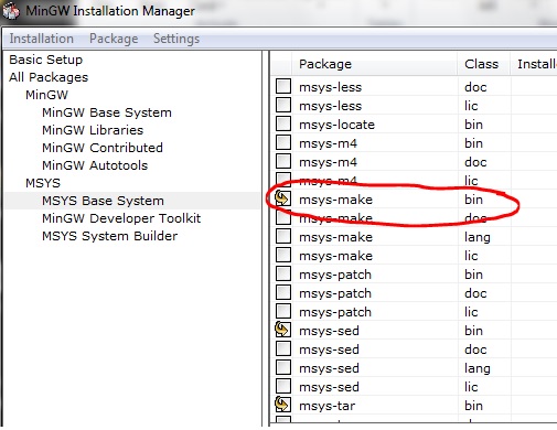
    At the moment, I think that enabling you to rebuild the utility is the best way forward so that you can modify the utility to meet your requirements. You don`t need to learn extensively about MinGW to rebuild the utility. The MingGW environment is only required as the tools and the example has a make based environment that requires make and mysys environment on windows.

    To set this up, you can download MinGW from here:

    and in the installation manager select the basic setup as follows and  in the msys package select msys-make, msys-bash, msys-bison on top of the basic setup. The installer will auto select the dependencies.

    After this you can simply simply set the path in the setupMsysEnv.bat,  run the .bat file  and the execute make clean and make all in the spiboot_test folder.

    Regards,

    Rahul 

    PS: I have updated the romparse with your feedback so please pull in the new updates.

    Here are the updates:

    • Changed CSEL condition to if ((value < 0) || (value > 3)) then report error
    • File size has been increased from 32 KB to 32MB by changing MAX_DATA_LEN_32bit  in romparse.h
    • PCI_EEAI_PARAM_SIZE

    romparse_updated.zip 

  • Rahul,

    Thanks for your kindly help!

    I will try to build MinGW by myself.

    Now a small program can boot to flash the LEDs,  thanks to your help.

    Like SPI boot on 6670, next step is to config the DDR. I have a .gel file, the question is how to config the boot DDR configuration table from my gel file.

    Q1. There are DDRA and DDRB to be configured ,are they share the same DDR boot configuration table (Table 8-26 of 6638K2K datasheet)?

    Q2. At the end of  "Table 8-26 DDR3 Boot Parameter Table"  there is a  "Chip Config" value, offset 120-376 . Its details is not explained in the datasheet.But I do see there are some configurations in the "Keystone II Boot examples" in the file /cfg/ddrConfigTable.h. So can you tell me the details of that "Chip Config"? There are 64 UINT32 value.

    Q3. Except that "Chip Config", I am afraid there are still some registers can not find in the .gel file or in  "KeyStion II DDR3 Memory Controller User Guide", such as  IpDfrNvmTiming,  iODFTTestLogic, readIdleCtl,   sysVbusmIntEnSet ,proClassSvceMap, mstId2ClsSvce2Map and .....

    In turn,  there are also some registers of the DDR3 controller user guide missed in the boot DDR  configuration table.

    So problem is:  there are some mismatch between the DDR boot config table and the DDR Controller user guide(or .gel file). How to config the "BOOT_EMIF4_TBL  emif4vCfg" table?

    Q4. MOST IMPORTANT:

    Hereby I paste my  .gel file , can you please help  config the DDR config table or ask the DDR and boot experts for help?

    locate to the function  "ddr3A_64bit_DDR1333_setup()" and "ddr3B 16bit_DDR1333_setup()";

    Thanks a lot !!!

    BR,

    Frank

    --------------------

    below is the gel file: 

    Frank_6638_K2K.gel

  • Frank,

    Good to hear that you are able to make progress with this.

    Do you have a local TI contact that you are working with. We would like to understand your use case for using the DSP boot master feature on the K2K device to provide further inputs on this issue. All of the software supported in our SDKs are so far targeted to support the ARM boot master usecase so we are just trying to make sure that you wont run into  issues after getting your system booted up.  Can you please help answer the following questions.

    • Are you planning to use the ARM core on the K2K device?
    • Will the ARM and the  DSP code run independently or are you planning to use the IPC mechanism to communicate between the DSP and the ARM cores.
    • Do you use your own secondary bootloader code or are you planning to use the device BootROM to load all the code corresponding to all the cores??

    Now, let me answer your questions:

    Frank Deng said:
    Q1. There are DDRA and DDRB to be configured ,are they share the same DDR boot configuration table (Table 8-26 of 6638K2K datasheet)?

    The DDR configuration table is checked by the boot ROM after every section load. If the ROM code detects that the table has become populated then the DDR3a is configured. After this memory can be loaded directly to DDR3a from the boot ROM. There is no equivalent configuration for DDR3b

    Frank Deng said:
    Q2. At the end of  "Table 8-26 DDR3 Boot Parameter Table"  there is a  "Chip Config" value, offset 120-376 . Its details is not explained in the datasheet.But I do see there are some configurations in the "Keystone II Boot examples" in the file /cfg/ddrConfigTable.h. So can you tell me the details of that "Chip Config"? There are 64 UINT32 value.

    If you checked the Keystone II ARM boot examples, then you can see that this is what the chipconfig registers correspond to:

    0x0000FF81, /* PIR */               // chipConfig[0]
    0, /* PGCR0 */                              // chipConfig[1]
    0x0280C4A5, /* PGCR1 */        // chipConfig[2]
    0x00F03D09, /* PGCR2 */        // chipConfig[3]
    0, /* PGSR0 */                              // chipConfig[4]
    0, /* PGSR1 */                            // chipConfig[5]
    0x42C21590, /* PTR0 */        // chipConfig[6]
    0xCFC712B3, /* PTR1 */
    0, /* PTR2 */
    0x04430D40, /* PTR3 */
    0x06413880, /* PTR4 */
    0x2800040B, /* DCR */
    0x008F6633, /* DTPR0 */
    0x12820180, /* DTPR1 */
    0x50022A00, /* DTPR2 */
    0x00001620, /* MR0 */
    0x00000006, /* MR1 */
    0x00000040, /* MR2 */
    0x710035C7, /* DTCR */
    0, /* DX0GCR */
    0, /* DX1GCR */
    0, /* DX2GCR */
    0, /* DX3GCR */
    0, /* DX4GCR */
    0, /* DX5GCR */
    0, /* DX6GCR */
    0, /* DX7GCR */
    0, /* DX8GCR */
    0x000DC000, /* PLLCR */     ChipConfig [28]
    0x0000007B, /* ZQ0CR1 */    ChipConfig [29]
    0x0000007B, /* ZQ1CR1 */    ChipConfig [30]
    0x0000007B, /* ZQ2CR1 */    ChipConfig [31]

    0, 0, 0, 0, 0, 0, 0, 0,
    0, 0, 0, 0, 0, 0, 0, 0,
    0, 0, 0, 0, 0, 0, 0, 0,
    0, 0, 0, 0, 0, 0, 0, 0 /* LSW values, none used */

    Frank Deng said:
    Q3. Except that "Chip Config", I am afraid there are still some registers can not find in the .gel file or in  "KeyStion II DDR3 Memory Controller User Guide", such as  IpDfrNvmTiming,  iODFTTestLogic, readIdleCtl,   sysVbusmIntEnSet ,proClassSvceMap, mstId2ClsSvce2Map and .....

    The BootROM only provides options to do the basic DDR configuration if you want to use advanced DDR controller features, you should do this using your application code.

    Frank Deng said:

    Q4. MOST IMPORTANT:

    Hereby I paste my  .gel file , can you please help  config the DDR config table or ask the DDR and boot experts for help?

    I recommend that you use the TI provided GEL file and test this feature on the TI EVM before trying this on the custom platform. This will help you understand how the configuration table needs to be populated for your custom platform. You can use the K2E examples in the ARM boot examples we provide as reference as we have tested those DDR configuration values.

    Regards,

    Rahul

  • Hi Rahul,

    Thanks for you reply.

    1.  Do you have a local TI contact that you are working with?

    Frank: We are not a big company. Without big chip order, FAE is not available.

    Because we successfull boot 6670 through SPI, with the former experience of 6670. I think the success on spi boot  of 6638 will not be too far away.  (currently DDR config the is last issue)

    2.The .gel files was valified before, no problem. Next step is how to config the ddr boot configuration table.

    3.Are you planning to use the ARM core on the K2K device?

    (1) Yes,we will use the ARM core but we did not use ARM before. One of my colleague is studying the 6638 ARM core now. But it won't be a short time before we can use it.

    (2) Currently we are transplanting the project from 6670 to 6638 in our products. So currently DSP is used only.(That's why I didn't mention anything about ARM core or ARM masterd boot)

    4.Will the ARM and the  DSP code run independently or are you planning to use the IPC mechanism to communicate between the DSP and the ARM cores.

    (1) We did not use ARM and DSP together before, so we are about to  study the scenario to be applied later, maybe independently or maybe not. Do you have any advice? or do you have any documents explain how to design the  implementation of DSP and ARM core?

    (2)Currently I only know the IPC mechanism to triger the DSP corepac1..7 and ARM core from DSP corepac0 , is there any other mechanism? How to boot the ARM core and dsp core when they are running independently?

    (3)Would it be more complex if we use ARM code as the boot master?  I think it would be more flexible if ARM mastered. But consider the bad documentation and examples without essential details, It would not be easy to use ARM mastered case. I have briefly review the ARM boot user guide and sadly finding there are also shortage of details.

    5. Do you use your own secondary bootloader code or are you planning to use the device BootROM to load all the code corresponding to all the cores??

    (1) Currently I  use the device BootROM to load all the code corresponding to all the cores and use magic addres and IPC trigger.

    (2) Secondary bootloader code: I thought of it before,I think this case would be more flexible, maybe the general steps would be:

    -use BootROM to boot a secondary boot code  in corepac0

    -in the secondary boot code:

       -- initialize  SPI and related config

       -- transter code from FLASH to L2 and DDR( I have understand the image .bin file structure before I can load the  Flash code to L2 and DDR memory correctly. )

       --jump to the APP point and use IPC to trig other cores.

    Do you have an example with secondary bootloader code?  The secondary bootloader code would cost our L2 memory, so if BootROM works,  secondary bootloader code is not the best choice.Do you have any advice?

    Thanks!

    Regards,

    Frank

  • Rahul,

    The ddrConfigTable in Keystone II boot example is only for emif4Vcfg, but 6638 datasheet demonstrated the ddr config table is emif4cfg, you can see they are different in Tiboot.h;

    Can you please explain the defination chipconfig[64] details of emif4cfg but not emif4Vcfg?

    Thanks!

    Regards,

    Frank

  • Frank,

    This seems to be an issue with the datasheet. I can confirm that all Keystone I devices (C667x , C665x) devices using the emif4cfg and all Keystone II devices 66AK2XX and TCI66xx devices use emif4Vcfg due to the updated EMIF IP used on the SOC.

    I will file a literature bug to get this fixed. 

    Regards,

    Rahul

  • Rahul,

    I found a lot of bugs of TI docs or device deisgn mistakes(warm reset still re-latch to DEVSTAT,which is not the desired action), and utilites bugs.

    Can TI give an offical award such as "BUG-FIND STAR AWARD" to me ? or hire me as the TI BUG-FIND part-time employee?

    hahaha.... lol

    BTW, toooooooo many literature bug and code bugs...

    Last week I feedback the literature and TI support conditon to Miss Sandy Hu and Mr. Rich Templeton. They promised me to have a talk to the literature department. But, who knows...

    Currently ,I sitll have to come to you if I meet with problems.Thank you!

    Regards,

    Frank