This thread has been locked.

If you have a related question, please click the "Ask a related question" button in the top right corner. The newly created question will be automatically linked to this question.

6638K2k SPI boot problem (continued 4th) - DDR configuration

Hi Rahul,

(Rahul knows best about my project situation)

Background is here, 6638 DSP SPI boot.

I am afraid it does not work when I put a DATA_SECTION for ddrConfigTable same as I did on 6670!

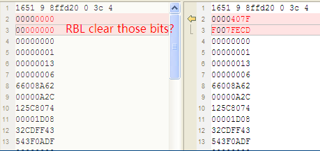
1) .gel file is verified with emulator, data/ addrss bus walking test is OK, all space addres read and write is ok when use emulator.

2)All the registers in .gel file have corresponding values in the ddrConfiTable ;

3) In 6670, I remembered when use this DATA_SECTION to config the DDR, most DDR space can be accessed and the only a small amoun of space  are not normal. BUT, in 6638, I can not even access any ONE address. In my application, I  juse write One address and read it back, and Flash the LED to indicate the success, but failed.

Of course , the data/address bus walking test and address filling test was also failed. 

Q1,Please please confirm is it the same usage to use a DATA_SECTION to config the ddr during boot? Is there is a configuration table for 6638 SPI boot now? I know it is not available in 6670. 

Q2.Please please confirm the ddrConfigTable structure, you said there is a lierature issure, please double check  and send me the structure in ROM source code, only the ROM source code is reliable! (please double check the source code, do not beleive any docs,you have seen that I have discovered so many document issues now) (I was told the 6638 ROM source code can not opened, but you can copy the ddrConfigurationTable part and the other SPI boot related part to me, not the whole ROM code.)

Please please confirm!

Please confirm!

Please!

Thanks!

Regards,

Frank

  • Frank,

    Yes, I confirmed that their is a literature bug in K2K datasheet for the DDR configuration table and also confirmed that the emif4vcfg is the correct DDR configuration table for K2K. The tiboot.h is a common header file used by DSP boot master and ARM boot master for configuring boot parameter tables and DDR Configuration table. It is my understanding that you have the tiboot.h from the K2 ARM Boot examples. If that is not the case, I am attaching the tiboot.h file for your reference.

    tiboot.h

    Initializing the DDR configuration table has also been demonstrated in the ARM bootloader examples for K2 devices.Have you looked at the file ddrConfigTable.h in 

    Keystone2_boot-examples\examples\k2e\cfg and Stage1.c file in the Keystone_boot-examples\examples\src\multiStage folder.

    This will demonstrate the usage of the DDR configuration table.

    The EMIF IP on this device is same as K2K device that you are using so you should be able to do the same on your device. The only difference is that for DSP boot master on K2H or K2K, you need to load the DDR configuration table at 0x008ffd20. For ARM boot master the DDR configuration table is loaded at 0x0c5a6e00.

    Hope this helps

    Regards,

    Rahul

  • Rahul,

    Thanks for your reply!

    Q1. What is EMIF_IP?  I searched the example code and found none, neither the datasheet and user guides. Where should I config the EMIF_IP, any example? My chip is 6638K2K, but there are only K2E K2H K2L example.

    Q2.My chip is 6638K2K, which example folder should I take for reference,K2E or K2H?

    Q3.In the Stage1.c, see the code below, what is the absolute address of “romtMainEmif4Cfg_addr”? I searched all the CSL codes and found none. I can not build successfully when I invoke the romtMainEmif4Cfg_addr.

    /* ROM table call to initialize DDR (Only defined in K2E/K2L) */

    #ifdef K2E

    extern unsigned int romtMainEmif4Cfg_addr;

    #endif


    Q4.  what is the absolute addr of "romtBootReentry_addr"? Maybe 0x20b00000? 

    fcn = (void (*)(void))&romtBootReentry_addr;


    Q5. I found there would be problem in the Stage.c code, both the single and multisatege.

    Look,

    at the end of the main() , it  will always jump to (void (*)(void))&romtBootReentry_addr  to reboot, and it will reboot -> boot load the image - main() execute - reentry to reboot, and reboot and reboot , it is a dead loop! can you exmplain the mechanism when it will break the dead loop and where would it jump to? It have no chance to go to other image or function during singlesatage boot or multistage case. 

    May be you will notice there is a modify to the MAGIC ADDR. But we must be clear that this Address will be overwritten at the end of the boot process(the entry point is defined in the image, start of the boot table). This address modify is useless.


    Q6, We are clear that if we have a DATA_SECTION in the 0x8FFFD20 in our image(I did it in 6670, it works), the ROM code will config the ddr (config the register defined in the enable bitmap), so why should it have a "reentry" to romtMainEmif4Cfg_addr to config the ddr manully in the user application? I thought the ddr would be configured by the ROM, so please please doublecheck if it is the same mechanism to config the ddr as 6670: locate a datasection in image, and the ROM will config the DDR, no need to invoke the romtMainEmif4Cfg_addr function manually.

    If it is the case, there is no need to reentry to the  romtMainEmif4Cfg_addr!!

    Please doublecheck,

    Thank you!

    Regards,

    Frank

  • Frank Deng said:
    What is EMIF_IP?  I searched the example code and found none, neither the datasheet and user guides. Where should I config the EMIF_IP, any example? My chip is 6638K2K, but there are only K2E K2H K2L example.

    EMIF IP refers to the intellectual property on the K2K SOC that is used to interface with DDR memory.

    Frank Deng said:
    Q2.My chip is 6638K2K, which example folder should I take for reference,K2E or K2H?

    K2K devices are specialized devices for communication infrastructure. I have only worked on K2H and K2E  and know that they have the same DDR configuration table as K2K so either one of them will work. I don`t think, that package is initializing DDR for the K2H examples.Please look at the K2E examples only to see how the DDR configuration table is populated. You can continue to place the DDR configuration table as you did in C6670 using pragma statements.

    There are differences between K2E and K2K in RAM memory map of the bootROM  and the romtable doesn`t have the function _romtMainEmif4Cfg. I would recommend you to only refer to the examples to see how the DDR configuration table is populate and not use romtMainEmif4Cfg as it doesn`t apply to your device.

    Frank Deng said:
    Q3.In the Stage1.c, see the code below, what is the absolute address of “romtMainEmif4Cfg_addr”? I searched all the CSL codes and found none. I can not build successfully when I invoke the romtMainEmif4Cfg_addr.

    As I mentioned in my earlier response, romtMainEmif4Cfg is not supported on K2H and K2K. This was added to the bootROM call table in K2E and K2L. The rom call table functions romtMainEmif4Cfg and romtBootReentry have been documented on the Keystone ARM bootloader examples wiki. It can also be found the linker command file Stage1.cmd in the package. Those addresses only apply to the ARM Boot master. For DSP bootROM, here are the address

    20b00000 _romtReInit
    20b00008 _romtBootReentry
    20b00010 _romtBtblInit
    20b00030 _romtEnableModule
    20b00038 _romtDisableModule
    20b00050 _romtConfigPll
    20b00058 _romtDelay
    20b00060 _romtDeviceFreqMhz

    Frank Deng said:
    Q4.  what is the absolute addr of "romtBootReentry_addr"?

    Please see my response above.

    Frank Deng said:
    I found there would be problem in the Stage.c code, both the single and multisatege

    No, this is not a dead loop. In the examples where we call the romRe-entry, we change the boot parameter table so that the boot rom will load the second stage(Stage2) from an offset in the flash memory. The Magic address will then be populated with the entry point of Stage2 that will load in DDR memory.

    Frank Deng said:
    We are clear that if we have a DATA_SECTION in the 0x8FFFD20 in our image(I did it in 6670, it works), the ROM code will config the ddr (config the register defined in the enable bitmap), so why should it have a "reentry" to romtMainEmif4Cfg_addr to config the ddr manully in the user application? I thought the ddr would be configured by the ROM, so please please doublecheck if it is the same mechanism to config the ddr as 6670: locate a datasection in image, and the ROM will config the DDR, no need to invoke the romtMainEmif4Cfg_addr function manually.

    There are 2 ways of initializing DDR on K2E, one is to use the rom call table function romtMainEmif4Cfg and the other is to use DATA_SECTION as you described.  On K2K, since  romtMainEmif4Cfg is a ROM internal function it can`t be called from the application code,  you will need to use the DATA_SECTION as you did with the C6670 device. In the examples, we used the romtMainEmif4Cfg and romRentry as that was a new feature introduced on K2E.

    Regards,

    Rahul

  • Rahul,

    Thanks for your patient explaination,I am much clear about the DDR configuration machanism now.

    Yes, now I did as what I did with the C6670.But still the DDR is not well configured.

    1) .gel file is double-checked, the .gel file can well configured the DDR;

    2) ddrCfgTable: all values referenced from .gel file.

    Q1    I found there is a issue.

    I connect to the device via emulator to see the ddrCfgTable value in 0x8ffd20 after reset .

    You will find the first three UINT32 are cleared, so please check if they are cleared by the RBL or should I have some other values not well configured?

    These three UINT32 are so important, they are enable bitsmap.(All the other values are not cleared and correct)

    Please have a try and check the RBL code to make sure the operation.

    Furthermore, how can I make sure the RBL have execute the DDR config function or not? 

    [update after Q1]

    I have studied the BootROM_c6670_PG1.0 code and found there is a mainEmif4Cfg() function to config the DDR.It demonstrates if there is any config function branch returns non-zero value, the configselect value will be set to 0; so I assume that my three UINT32 configselect to be set to 0 is just this case.But, the values are all from the gel file(gel file is varified), how can I find where  the problem is? So please send my the RBL source code that related with ddr config.

    And it does not make sense that the 6638K2K ROM source code is not open to us ---- the end users, with undetailed docs and uncomplete examples. Our implementation will get more smoothly if we have the source code.

    ----------------------------------------

    Q2.

    How to config two parameter table(one for stage 1 and the other for stage 2) in the spi.map file?

    I have try to write two sections in the .map file but it generate two series of parameter tables(each consist of eight parameter tables), but what i want is just one series of parameter table.

    Can you please ask the romparse anthor about this issue and have a try to config two parameter table to implement multistage boot?

    Thanks in advance!

    Regards,

    Rahul

  • Frank,

    Can you please share your code here so that we can reproduce the issue on a K2K or K2H EVM.

    I have another suggestion that you can try and might help you easily debug your DDR configuration issue. Since you have simple code booting in to MSMC, you can initialize the DDR using PDK functions from code loaded in MSMC and then re-enter the bootROM to load the rest of the code.  This scheme is similar to the multi-stage boot that we used in the K2E but instead of using DDR configuration table and ROM to initialize DDR, you will use PDK function.

    This will require you to create 2 boot image one that will load into MSMC and initialize DDR and the second image that will execute from DDR. You can write the first image at the base of the flash memory and the second image at an offset from the base. Before you re-enter the bootROM, you can change the offset from which ROM will read the image to load the second stage by changing the read_addr_msw and read_addr_lsw in the boot parameter table. Check the setting in the file paramsTable.h

    (STAGE_2_BRANCH_ADDRESS >> 16) & 0xffff,	/* The base address to read from the SPI, upper 16 bits */
    (STAGE_2_BRANCH_ADDRESS & 0xffff),      	/* The base address to read from the SPI, lower 16 bits */

    Based on you request, I am sharing the ddr configuration code that is part of the bootROM.

    /*
     *
     * Copyright (C) 2011 Texas Instruments Incorporated - http://www.ti.com/ 
     * 
     * 
     *  Redistribution and use in source and binary forms, with or without 
     *  modification, are permitted provided that the following conditions 
     *  are met:
     *
     *    Redistributions of source code must retain the above copyright 
     *    notice, this list of conditions and the following disclaimer.
     *
     *    Redistributions in binary form must reproduce the above copyright
     *    notice, this list of conditions and the following disclaimer in the 
     *    documentation and/or other materials provided with the   
     *    distribution.
     *
     *    Neither the name of Texas Instruments Incorporated nor the names of
     *    its contributors may be used to endorse or promote products derived
     *    from this software without specific prior written permission.
     *
     *  THIS SOFTWARE IS PROVIDED BY THE COPYRIGHT HOLDERS AND CONTRIBUTORS 
     *  "AS IS" AND ANY EXPRESS OR IMPLIED WARRANTIES, INCLUDING, BUT NOT 
     *  LIMITED TO, THE IMPLIED WARRANTIES OF MERCHANTABILITY AND FITNESS FOR
     *  A PARTICULAR PURPOSE ARE DISCLAIMED. IN NO EVENT SHALL THE COPYRIGHT 
     *  OWNER OR CONTRIBUTORS BE LIABLE FOR ANY DIRECT, INDIRECT, INCIDENTAL, 
     *  SPECIAL, EXEMPLARY, OR CONSEQUENTIAL DAMAGES (INCLUDING, BUT NOT 
     *  LIMITED TO, PROCUREMENT OF SUBSTITUTE GOODS OR SERVICES; LOSS OF USE,
     *  DATA, OR PROFITS; OR BUSINESS INTERRUPTION) HOWEVER CAUSED AND ON ANY
     *  THEORY OF LIABILITY, WHETHER IN CONTRACT, STRICT LIABILITY, OR TORT 
     *  (INCLUDING NEGLIGENCE OR OTHERWISE) ARISING IN ANY WAY OUT OF THE USE 
     *  OF THIS SOFTWARE, EVEN IF ADVISED OF THE POSSIBILITY OF SUCH DAMAGE.
     *
    */
    /*****************************************************************************************
     * FILE PURPOSE: DDR3 top level interface
     *****************************************************************************************
     * FILE NAME: mainemif4.c
     *
     * DESCRIPTION: Peform DDR3 configuration
     *
     *****************************************************************************************/
    #include "bootconfig.h"
    
    #ifdef BOOTCONFIG_INCLUDE_EMIF4
    
    #include "types.h"
    #include "tiboot.h"
    #include "device.h"
    #include "emif4_api.h"
    #include "rmain.h"
    #include "pscapi.h"
    #include "cfgpll_api.h"
    #include "bootlog.h"
    #include "bootTrace.h"
    
    #include <string.h>
    
    #pragma DATA_SECTION (emif4Table, ".ddr3Table")
    #pragma DATA_ALIGN (emif4Table, 4)
    
    #ifdef DEVICE_EMIF4_REV_EMIF4V
     BOOT_EMIF4V_TBL_T emif4Table;
    #else
     BOOT_EMIF4_TBL_T emif4Table;
    #endif
    
    #ifdef BOOTCONFIG_N_BOOTLOG_ENTRIES
     #pragma DATA_SECTION (fname, ".fname")
     #pragma DATA_ALIGN (fname, 4)
     static char const fname[] = __FILE__;
    #endif
    
    /*****************************************************************************************
     * FUNCTION PURPOSE: Configure the DDR3 interface
     *****************************************************************************************
     * DESCRIPTION: The DDR3 interface is configured only if the conig select mask
     *              is non-zero.
     *****************************************************************************************/
    SINT16 mainEmif4Cfg (void)
    {
        SINT16 ret = 0;
    
        bootTrace (0);
    
        if ((emif4Table.configSelect_msw  == 0)   && 
            (emif4Table.configSelect_slsw == 0)   &&
            (emif4Table.configSelect_lsw  == 0))
            return (0);
    
        if ((emif4Table.configSelect_msw & BOOT_EMIF4_ENABLE_MSW_pllCtl) != 0)  {
    
            ret = chipCfgDdrPll (DEVICE_DDR_PLL_BASE, chipLower16(emif4Table.pllPrediv),
                                 chipLower16(emif4Table.pllMult), chipLower16(emif4Table.pllPostDiv),
                                 (UINT32)chipCoreFreqMhz(), DEVICE_MIN_DDR_FREQ_MHZ,
                                 DEVICE_PLL_OUTSRC(DEVICE_DDR_PLL_NUM));
            if (ret != 0)
                bootLogEntry ((char *)fname, __LINE__, ret);
    
        }
    
       
        if (  ((emif4Table.configSelect_msw & (BOOT_EMIF4_ENABLE_ALL_MSW ^ BOOT_EMIF4_ENABLE_MSW_pllCtl)) == 0)  &&
               (emif4Table.configSelect_msw == 0)   )    {
            emif4Table.configSelect_lsw = 0;
            return (ret);
        }
    
        ret = chipPowerEmif4 ();
        if (ret != 0)  {
            emif4Table.configSelect_msw  = 0;
            emif4Table.configSelect_slsw = 0;
            emif4Table.configSelect_lsw  = 0;
            bootLogEntry ((char *)fname, __LINE__, ret);
            return (ret);
        }
    
    
        ret = chipConfigEmif4Phy ((void *)&emif4Table);
        if (ret != 0)
            bootLogEntry ((char *)fname, __LINE__, ret);
    
        ret = chipConfigEmif4 (DEVICE_EMIF4_BASE, &emif4Table);
        if (ret != 0)
            bootLogEntry ((char *)fname, __LINE__, ret);
    
    
        emif4Table.configSelect_msw  = 0;
        emif4Table.configSelect_slsw = 0;
        emif4Table.configSelect_lsw  = 0;
    
        return (ret);
    
    } /* mainEmif4Cfg */
    
    
    /******************************************************************************************
     * FUNCTION PURPOSE: Initialize the DDR3 table
     ******************************************************************************************
     * DESCRIPTION: The DDR3 table is initialized.
     ******************************************************************************************/
    SINT16 mainEmif4Params (void)
    {
        bootTrace (0);
    
        chipDefaultEmif4Table((void *)&emif4Table);
        
        return (0);
    
    } /* mainEmif4Params */
        
    #endif /* BOOTCONFIG_INCLUDE_EMIF4 */


    I will check with the author of the utility but as far as I know the romparse utility is currently designed for adding only one parameter table. We have provided the romparse utility in the source, so you should be able to modify the utility to meet your usecase. or you can create another utility to post process the output of romparse to add the additional parameter table.

    Regards,

    Rahul

  • I did some experiments with  the romparse utility and was able to add multple boot parameters to the image using the map file attached below:

    https://e2e.ti.com/cfs-file/__key/communityserver-discussions-components-files/791/3426.spirom.map

    Please give this a try and let me know if you see any issues.

  • Rahul Prabhu said:

     create 2 boot image one that will load into MSMC and initialize DDR and the second image that will execute from DDR

    I already have this solution in my mind before I post this question, (can you remember that I made a two image back up boot solution on 6670?similar to this solution), but I would prefer to init the DDR by ROM ,because refer to the .gel file, all the registers to be configured are included in the ddrConfigTable, so I assumed there is no need to have a second initialization in the my user application code if the ROM- ddr- init works. But by now, I am afraid you can not push on this issues more.  From studying the mainemif4Cfg.c , it is clearly the configSelect values are cleared because return err values during configuration, but there is no way to debug the operation ... 

    Rahul Prabhu said:

    I did some experiments with  the romparse utility and was able to add multple boot parameters to the image using the map file attached below:

    (Please visit the site to view this file)

    Please give this a try and let me know if you see any issues.

    Add a section in the .map file to have another parameter table, it works, thank you!
    Rahul Prabhu said:

    20b00000 _romtReInit
    20b00008 _romtBootReentry
    20b00010 _romtBtblInit
    20b00030 _romtEnableModule
    20b00038 _romtDisableModule
    20b00050 _romtConfigPll
    20b00058 _romtDelay
    20b00060 _romtDeviceFreqMhz

    Can you explain each of the above function? Especially _romtReInit() and  _romtBootReentry() and _romtBtblInit()...

    I changed the dev_addr to my 2nd image offset as you suggested and jump to [20b00000 _romtReInit] or [20b00008 _romtBootReentry];
    but it just bootload the first image again and I connect emulator to watch 0x8FFF00, I found the dev_addr(in the Memory Browser)  was seccuessfully changed to the second image offset(NOTE! cache writeback opearation is essential). BUT, after BootReentry(), it reboot, and the dev_addr was overwritten as the first image offset,it still bootload the first image.

    Can you have a try? and please test on DSP master boot.

    I thought the parameter table is re-read from  the first 0x80 of FLASH memory, so it is useless to change the dev_addr before re-boot.

    So please explain the detail operation of  _romtReInit() and _romtBootReentry(). Which kind of values/registers will be changed?

  • Hi Frank,

    Thanks for confirming that you can append multiple boot parameter tables to the boot image using romparse utility.

    The explanation for ROM call table functions is provided here:

    With romtReInit, the ROM will reset all of it is states, clock settings, and reinitialize the boot parameter table from the boot switches,etc. 

    With romtBootReentry, the device will not change the PLL unless you provide a new boot parameter table with updated clock settings. This function is typically used in boot scenarios where you want to change the default BootROM behavior while booting from a boot media. this is used by users when they want to speed up the boot peripheral clocks or you want to boot a second stage image from a offset in the flash media.

    In this multistage boot scenario, users will need to change the boot parameter table that is used by the boot ROM appropriately to chnage the behaviour or the device setting. For example in SPI boot mode the bootROM boot from SPI peripheral with PLL in bypass with SPI clock at 100Khz. By providing the appropriate PLL multplier and divider settings and prescale values, you can re-enter boot ROM using romtReentry() and force the BootROM to configure the PLL and use a higher SPI clock to boot.

    Same way, in your scenario, you can change the flash offset from which the second stage boot image is read from the default 0x0000000 (daefult is base of flash memory) to a different offset from which the second stage can be read in.

    Inorder for me to reproduce your issue, we would appreciate if you can share your example code so that we can try and replicate the same on the EVM.

    Regards,

    Rahul

    PS: I have sent you an offline message to get some details. Can you please respond to that email so that we can get you some local help on this issue.

  • Rahul,

    I understand that I can change the parameter table in L2, which is located in 0x8FFF00;

    My image and the similar application and problem is drawn below.

    I already have a workaround now.

    But can you point out why the dev_addr is re-read from the FLASH (start 0x80 bytes, which is the parameter table0 in the)? Actually, I tested and found not only the dev_addr , the other values we changed by our application image1 will all overwritten after re-enter boot.

    Please have a test.