This thread has been locked.

If you have a related question, please click the "Ask a related question" button in the top right corner. The newly created question will be automatically linked to this question.

[AM5728] DPI Video Output frequency

Guru 24520 points

Hi TI Experts.

Please let me confirm the following question.

[Question]
Would you please teach me the reason why there is the difference for specification between "Table 7-15. DPI Video Output i (i = 1..3) Default Switching Characteristics" and "Table 7-16. DPI Video Output i (i = 1..3) Alternate Switching Characteristics"?

My customer would like to use the 148MHz DPI clock. In case of Table7-15 specification, they cloud not use this clock for  tc because the out of range of tc specification.

If you have any questions, please let me know.

Best regards.

Kaka

  • I have forwarded this to the factory team.
  • Hi Biser,

    Thanks for your quick response. I am waiting for factory team feedback.

    Best regards.
    Kaka
  • Kaka said:
    Would you please teach me the reason why there is the difference for specification between "Table 7-15. DPI Video Output i (i = 1..3) Default Switching Characteristics" and "Table 7-16. DPI Video Output i (i = 1..3) Alternate Switching Characteristics"?

    This was how TI defined this operational mode.  What device are you connecting to, and at what frequency do you plan to operate?  Is it a 1.8V or 3.3V interface?

  • Hi Bard,

    Would you please explain about the difference of operation mode?
    Now I do not have information about they will be connecting to AM572x.
    For frequency, they would like to use the 148MHz DPI clock as I said in my first post.
    For interface voltage, also we do not have this information...

    Do you need those information(Connecting device, voltage for interface) to answer?

    If you have any more questions, please let me know.
    Best regards.
    Kaka
  • At lower speeds, most interfaces work by having the transmitter launch data on one edge, while the receiver latches it on the opposite edge. In this scenario setup/hold times are centered on the receiving edge. In this scenario you are only using HALF of a cycle from launch to sample.

    At higher speeds, the cycle times become too small to meet setup/hold requirements. In this case, most devices use the FULL cycle for timing. In this case, the timings are skewed to no longer be centered on the edge. In this case, the transmitter launches on one edge and the receiver latches on that SAME edge a full cycle later. For this to work, the transmitter's minimum output delay needs to be larger than the receiver's hold requirements.

    So that's the background on why we have chosen these timings. Can you please tell me the specific device that won't work with these timings? I wanted to look at the device's data sheet to verify whether or not it might work. Often times I find customers thinking in terms of "half cycle timings" and not understanding to think of the interface in the context of "full cycle timings".

  • Hi Brad,

    Thank you for your comments.
    Please let confirm for understanding of "Default" and "Alternate". I drew the figure of those timings and attached it as below.

    DPI.pdf

    Would you please check whether my understanding is correct?
    By the way, would you please teach me the reason why the parameters of D5 and D6 on table 7-15 and table 7-16 are exchanging.
    And how customer change the mode of "alternate" from "default"?

    If you have any questions, please let me know.
    Best regards.
    Kaka
  • Kaka said:
    Please let confirm for understanding of "Default" and "Alternate". I drew the figure of those timings and attached it as below.

    No, that's not right.  Your diagram looks like DDR vs SDR.  The difference is whether the launching/sampling occur on the same edge or on opposite edges.

    Kaka said:
    By the way, would you please teach me the reason why the parameters of D5 and D6 on table 7-15 and table 7-16 are exchanging.

    This looks like a copy/paste error.  The "description" column looks right, but it looks like the "Parameter" values were flipped by mistake.  D5 and D6 have the same meaning across both tables.  I'll submit a correction.

    Kaka said:
    And how customer change the mode of "alternate" from "default"?

    This is determined by the Virtual or Manual I/O Mode as listed in Table 7-2 "Modes Summary".

  • Hi Brad,

    I got feedback from my customer.
    They will connect the FPGA via DPI interface. And it is the 3.3V interface.

    Also thank you for your confirming for my understanding.
    But I could not understand that the difference of launching/sampling.
    Would you please provide more detail of them? Or it very helpful for us to understand your comment by providing the block diagram.

    Best regards.
    Kaka
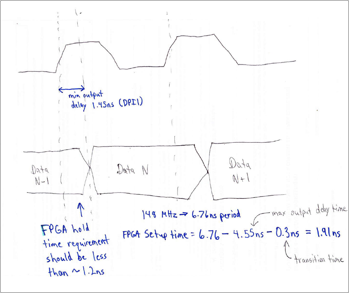
  • Ok, I drew a picture to try and make this clear:

    A few notes on the drawing:

    • Everything is based on rising edge in the diagram I drew. In other words, the expectation is that the FPGA is sampling the data on the rising edge, and also that the display port is configured to drive/launch data on the rising edge.
    • Looking at the first rising edge you can see that the FPGA would be sampling Data N-1.  On that same edge, the AM572x would launch Data N.
    • We specify that there will be a delay from the rising edge of 1.45ns.  I included a little extra margin to account for transition times, so if for example the FPGA hold time requirement is around 1ns, this should be fine.  I think 1.2ns is about the largest hold time that would work as shown in the diagram.
    • For the setup time I used the cycle period and subtracted the max output delay time.  That's the longest possible delay specified and so that number will be the worst case for use in computing the needed FPGA setup time.  So as long as the FPGA setup time is less than 1.91ns that timing should work fine.

    Brad

  • Hi Brad,
    Thank you for your response.

    To summary your comments, I understand the following.
    1. "Default" is "Virtual " in TRM. "Alternative" is "Manual I/O " in TRM.
    2. The difference between Default and Alternative is the adjusting of timing. "Default " is pre-set in AM572x. "Alternative" is Manual adjusting.
    So if they use the "Alternative" mode, they need to adjust the all i/o timing for DPI signals.

    Best regards.
    Kaka
  • Kaka said:
    1. "Default" is "Virtual " in TRM. "Alternative" is "Manual I/O " in TRM.

    The mapping of timings to modes is given in Table 7-2 "Modes Summary".  For rising edge reference, no virtual/manual mode is used.  For falling edge reference, DSS_VIRTUAL1 is used.  If you were using this mode, you would need to further consult Table 7-19 "Virtual Functions Mapping for Video Output Port" which tells you how to program the delay mode on a pin by pin basis.

    Kaka said:
    2. The difference between Default and Alternative is the adjusting of timing. "Default " is pre-set in AM572x. "Alternative" is Manual adjusting.
    So if they use the "Alternative" mode, they need to adjust the all i/o timing for DPI signals

    Yes, for alternative timings they would need to implement the Manual I/O mode as listed in Table 7-2 "Modes Summary".