Hi
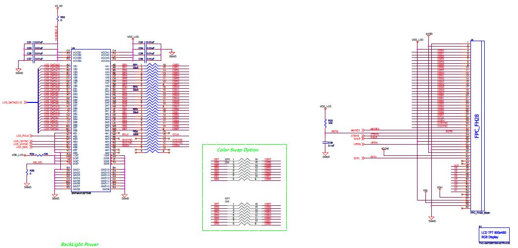
I have a question on the LCD pin mapping done in the evaluation board.
In the evaluation board LCDDATA23 is mapped to R0, LCDDATA4 to B7 and so on.
But according to the TI errata3.1.1, for 24 bit mode LCDDATA23 is B0 and LCDDATA4 to R7 and so on.
I understand that for 16bit mode R and B are to be swapped. But how can the LCD used in 24bit mode in evaluation board have the swapped configuration.
Kindly help.