This thread has been locked.

If you have a related question, please click the "Ask a related question" button in the top right corner. The newly created question will be automatically linked to this question.

DSK6713 Interrupt configuration questions

Other Parts Discussed in Thread: CCSTUDIO

Greetings community!

For our Digital Signal Processors class, we've been entrusted to develop a digital transmultiplexer. This implies we need to use two cards one for the multiplexing and other for demultiplexing the signal.

The thing is, that we need to synchronize both cards. For instance, we decided to use an external interrupt.

First, we'll turn on the receiver. It will keep on an infinite loop until it receives the external interrupt from the emitter, so it starts saving the received samples from the CODEC to process them and separate the signals. The algorithm was developed to support N channels, but due to the hardware limitations (mainly CODEC channels and CODEC sample rate, it was limited to 4 channels). We put a signal on the first ("0") channel via a microphone and receive via the same channel on the other side of the system.

The past week we succesfully tested the emitter and the receiver by separate, now we got to sync them. We will be able to test our sync method next monday.

So, as a quick-n-dirty solution we're using the EMIF port at the emitter to generate the transition needed for the interrupt (first putting it in an 0 to 1 or viceversa).

To receive the interrupt, we're using the EXT_INT4 pin on the J3 peripheral interface at the receiver card. It's connected via de GPIO, and we've already put the HPI_EN pin to the pull-down resistor via the dipswitch described HERE.

We've checked this great forum, with topics such as:

[C6713] Interrupt handling

C6713 GPIO Help!

GPIO Hardware Interrupts Question

And read these docs:

* spru584a - TMS320C6000 General Purpose I/O Reference Guide

* spru646a - TMS320C6000 DSP Interrupt Selector Reference Guide

* TMS320C6713 Datasheet

* DSK6713 Technical Reference

* C6713 Chip Support Library Guide

* spru733a - C67xx CPU and Instruction Set Guide (chapter 5 - Interrupts)


We're running on C6713 Code Composer Platinum v3.1 Note that we added all neccesary libraries (dsk init, dsk6713.cmd, bsl, csl... aic23, led...)


To test this, i made a simple program that would receive that interrupt turning on a LED and changing a flag value. I based it on what others have done in the mentioned forum threads.

First of all, our basic code to test if the interrupt is actually being processed:

// TMXReceptor.c     // IRQ test version

/*  // TMXReceptor.c
    UPIITA-IPN
    David VP
    Program used to test external interrupts
*/

// dsk6713_led.h and others are added to the project via code composer

#include "C:\CCStudio_v3.1\C6000\dsk6713\include\dsk6713_aic23.h"
Uint32 fs=DSK6713_AIC23_FREQ_32KHZ; // Tasa de muestreo CODEC
#include "C:\CCStudio_v3.1\C6000\dsk6713\include\dsk6713.h"
#include <stdio.h>
// #include <string.h>
#include <stdlib.h>
#include <math.h>
#include <time.h>
#include <csl_gpio.h>
#include <csl_gpiohal.h>
#include <csl_irq.h>
#include "db4_2etapas.h"

// M, N and sinc are defined in "db4_2etapas.h" apart from filters' coefficients.

// Global Variables (Variables globales)
int flag = 1;
int iter = 0;
int startflag = 0;
int outputflag = 0;
float abuffer[N] = {0}; // Buffer para recuperacion

GPIO_Handle gpio_handle;  /* handle para el GPIO - GPIO Handle*/

//Configuración de los registros del GPIO (GPIO Registers' Configuration)
GPIO_Config gpio_config = {       
    0x00000000, // gpgc = Modo Passthrough de Interrupciones y control directo sobre GP0
                // Passthrough Interruption mode and direct control over GP0
    0x0000FFFF, // gpen = Todos los pines de GPIO de 0 a 15 habilitados
                // All GPIO pins enabled (from 0 to 15)
    0x00000000, // gdir = Todos los pines de GPIO como entradas
                // All pins as inputs
    0x00000000, // gpval = Guarda el nivel lógico de los pines
                // Record logic level of the pins
    0x00000010, // Activar IRQ para pin 4
                // Enable IRQ at pin 5
    0x00000010, // Activar evento de irq para pin 4
                // Enable pin 4 EDMA irq event
    0x00000000  // gppol -- default state
                // Default - Rising edge
};

// This can be written to a separate .c file
irq_ext_enable(){
    // First, globally disable interrupts
    // CSR [Control Status Register] Bit 0 is GIE [Global Interrupt Enable]
    // Set last bit to ZERO
    CSR = (CSR)&(0xFFFFFFFE);
    // Set the NMIE bit (bit #1) at the IER
    IER |= 0x00000002;
    // Set the INT4 bit (bit #4) at the IER
    IER |= 0x00000010;
    // Last, globally enable interrupts (CSR last bit to 1)
    CSR |= 0x00000001;
}

main()
{   
    // Configure GPIO
  
    gpio_handle = GPIO_open( GPIO_DEV0, GPIO_OPEN_RESET );

    GPIO_config(gpio_handle,&gpio_config);

    // ENABLE EXTERNAL INTERRUPTS
    irq_ext_enable();

    comm_intr();             //init DSK, codec, McBSP
    DSK6713_LED_init();

    while(startflag == 0); // esperar a la sincronización del otro DSP

    while(1)
    {     
        while(flag == 1); // Wait for the CODEC interrupt to clear the flag

        if(iter > sinc) outputflag = 1; // Wait for #[sinc] samples then output the results

        // ###################################################
        // ALL THE ALGORITHM IS PUT HERE
        // ####################################################

    }   // End of infinite while (Fin del while infinito)

}        //end of main

interrupt void c_int04()             //ISR INT_EXT4
{
    startflag = 1; // Turn on the main program's flag
    iter = 0; // Reset the iteration counter
    DSK6713_LED_on(0); // Turn on the led
}

interrupt void c_int11()             //ISR
{
        inputbuffer = (float)((short)input_sample()); // Get a sample
        if(outputflag == 1) // If the interrupt was already received, output samples
        {
            output_sample((short)(outputbuffer)); // Output recovered signal
        }
        else // otherwise, output zeros
        {
             output_sample((short)(0)); // Output zero sample
        }
        flag = 0;             //set flag to resume algorithm flow
}


// TMXReceptor.c  End of File


After that, we've modified our vectors_intr.asm (got it from the book) just adding the details for the ext interrupt 4 to get handled by a function in our C code. It looks like this:

<<< File begins after this line >>>

*Vectors_intr.asm Vector file for interrupt INT11
   .global _vectors            ;global symbols
   .global _c_int00
   .global _vector1
   .global _vector2
   .global _vector3
   .global _c_int04            ; symbol for EXT_INT4
   .global _vector5
   .global _vector6
   .global _vector7
   .global _vector8
   .global _vector9     
   .global _vector10
   .global _c_int11              ;for INT11
   .global _vector12 
   .global _vector13  
   .global _vector14
   .global _vector15

   .ref _c_int00                ;entry address

VEC_ENTRY .macro addr            ;macro for ISR
    STW   B0,*--B15
    MVKL  addr,B0
    MVKH  addr,B0
    B     B0
    LDW   *B15++,B0
    NOP   2
    NOP  
    NOP  
   .endm

_vec_dummy:
  B    B3
  NOP  5

 .sect ".vecs"                ;aligned IST section
 .align 1024
_vectors:
_vector0:   VEC_ENTRY _c_int00       ;RESET
_vector1:   VEC_ENTRY _vec_dummy      ;NMI
_vector2:   VEC_ENTRY _vec_dummy      ;RSVD
_vector3:   VEC_ENTRY _vec_dummy
_vector4:   VEC_ENTRY _c_int04        ;INT04 Ext
_vector5:   VEC_ENTRY _vec_dummy
_vector6:   VEC_ENTRY _vec_dummy
_vector7:   VEC_ENTRY _vec_dummy
_vector8:   VEC_ENTRY _vec_dummy
_vector9:   VEC_ENTRY _vec_dummy
_vector10:  VEC_ENTRY _vec_dummy
_vector11:  VEC_ENTRY _c_int11        ;ISR address
_vector12:  VEC_ENTRY _vec_dummy
_vector13:  VEC_ENTRY _vec_dummy
_vector14:  VEC_ENTRY _vec_dummy
_vector15:  VEC_ENTRY _vec_dummy

<<< File ends the line before >>>


Is there anything I've missed? I've enabled the interrupt individually, I've enabled the GPIO pin and configured it as an interrupt, also set up the interrupt in the vectors_intr.asm file. The program gets compiled with no errors or warnings.

I'll be grateful for any advice!


- David


  • Just an update: What do you think about using interrupts in this project? Maybe we can use another method to sync the cards. Any ideas?

  • David VP said:
    int flag = 1;
    int iter = 0;
    int startflag = 0;

    Any variable that will be used as a flag in your program should be declared with the volatile modifier to alert the compiler to the fact that it may be changed by "external" events. Otherwise, the compiler may change or remove tests that it thinks are unnecessary.

    David VP said:
    _vec_dummy:
      B    B3
      NOP  5

    If you ever get one of the dummy interrupts, your program will get lost at this point. Change B B3 to B IRP, and make another one for NMI that uses B NRP.

    David VP said:
    The program gets compiled with no errors or warnings.

    I thought that the C default function return type is int, so I would have expected a warning or error when your irq_ext_enable() and main() functions do not return values. This must not be the case since you did not get an error for it. Just my misunderstanding.

  • Thanks Randy!

    About the volatile modifier, I used it in AVR C for the same means, thanks for reminding that crucial aspect !!!

    I didn't know that could happen with dummy vectors, I'll change it right now.

    I'll post the new vectors_intr.asm file ASAP for checking.

    -------------------

    Apart from this, is there any concern about how I enable interrupts in the main program? Like another register, hidden vector, anything.


    Thanks in advance!

  • Is it ok like this?


    vectors_intr.asm


    <<< File begins after this line >>>

    *Vectors_intr.asm Vector file for interrupt INT11
       .global _vectors            ;global symbols
       .global _c_int00
       .global _vector1
       .global _vector2
       .global _vector3
       .global _c_int04            ; symbol for EXT_INT4
       .global _vector5
       .global _vector6
       .global _vector7
       .global _vector8
       .global _vector9    
       .global _vector10
       .global _c_int11              ;for INT11
       .global _vector12
       .global _vector13 
       .global _vector14
       .global _vector15

       .ref _c_int00                ;entry address

    VEC_ENTRY .macro addr            ;macro for ISR
        STW   B0,*--B15
        MVKL  addr,B0
        MVKH  addr,B0
        B     B0
        LDW   *B15++,B0
        NOP   2
        NOP 
        NOP 
       .endm

    _vec_nmi:
      B    NRP
      NOP  5
      
    _vec_dummy:
      B    IRP
      NOP  5

     .sect ".vecs"                ;aligned IST section
     .align 1024
    _vectors:
    _vector0:   VEC_ENTRY _c_int00       ;RESET
    _vector1:   VEC_ENTRY _vec_nmi       ;NMI
    _vector2:   VEC_ENTRY _vec_dummy      ;RSVD
    _vector3:   VEC_ENTRY _vec_dummy
    _vector4:   VEC_ENTRY _c_int04        ;INT04 Ext
    _vector5:   VEC_ENTRY _vec_dummy
    _vector6:   VEC_ENTRY _vec_dummy
    _vector7:   VEC_ENTRY _vec_dummy
    _vector8:   VEC_ENTRY _vec_dummy
    _vector9:   VEC_ENTRY _vec_dummy
    _vector10:  VEC_ENTRY _vec_dummy
    _vector11:  VEC_ENTRY _c_int11        ;ISR address
    _vector12:  VEC_ENTRY _vec_dummy
    _vector13:  VEC_ENTRY _vec_dummy
    _vector14:  VEC_ENTRY _vec_dummy
    _vector15:  VEC_ENTRY _vec_dummy


    <<< File ends the line before >>>

  • David VP said:
    _vec_dummy:
      B    IRP
      NOP  5

    Some people like to have "dummy" ISRs trap so you can figure out quickly which interrupt occurred. In that case, you would have a separate one for each dummy interrupt and have it spin. This locks up the DSP which gets you to click Halt and find where you are and that an unexpected interrupt occurred. To do this you would replace B IRP with B $ and make a copy for each interrupt. Just a comment, not really a suggestion.

    David VP said:
    Apart from this, is there any concern about how I enable interrupts in the main program? Like another register, hidden vector, anything.

    In your enabling, you set IER for int04 but not int11 even though you have an ISR for it. Also, you enable NMI which I did not know was needed, and you do not want it to occur anyway since you have a dummy ISR for it.


  • RandyP said:

    Some people like to have "dummy" ISRs trap so you can figure out quickly which interrupt occurred. In that case, you would have a separate one for each dummy interrupt and have it spin. This locks up the DSP which gets you to click Halt and find where you are and that an unexpected interrupt occurred. To do this you would replace B IRP with B $ and make a copy for each interrupt. Just a comment, not really a suggestion.

    Now that makes a lot of sense. But now, I am debugging INT04 by turning on a LED, I guess that's enough for now.

    RandyP said:

    In your enabling, you set IER for int04 but not int11 even though you have an ISR for it. Also, you enable NMI which I did not know was needed, and you do not want it to occur anyway since you have a dummy ISR for it.

    Forgot to mention that comm_intr() is a function that enables int11 and configures the CODEC for this card. In the DOCs I mentioned in the first post, it indicates that for an external interrupt to be catched, one has to enable NMI first. NMI is not used but I read this was a requirement.

    I will be able to test the interrupt tomorrow, I'll let you know how it goes. Thanks!

  • It worked!!!

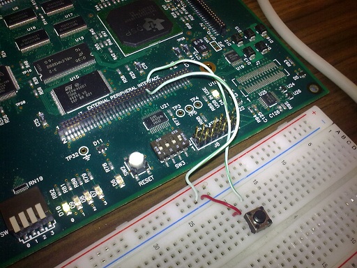
    I used a small pushbutton to short the INT04 pin to GND, so when I pressed it was taken to 0V then when released it went to Vcc again (by its pullup resistor) and the LED got turned on.

    Now, we're working on how to reproduce the pushbutton phisical behavior by the other DSP, using a transistor as a switch to generate that transition.

    Thanks a LOT for your advice!!! Hopefully I'll post the updated code later this week.

    - David VP

  • Excellent work you have done.

    Is there a GPIO pin that you can use from the daughtercard connector on one DSK to drive this signal on the other DSK? Unused pins from some peripherals may be used as GPIOs in some cases.

  • RandyP said:

    Excellent work you have done.

    Is there a GPIO pin that you can use from the daughtercard connector on one DSK to drive this signal on the other DSK? Unused pins from some peripherals may be used as GPIOs in some cases.

    Well, that would be an option but: As we've experimented before, if we put 3.3V directly to the INT04 pin, it causes a major failure in the DSK (it appears to "halt", caused by the pullup resistor, as specified in the datasheet) and gets disconnected from Code Composer, requiring it to be power-cycled.

    As far as I'm aware of, if one uses GPIO pins as outputs (I've come across several forum posts and articles about that topic) only  0V and 3.3V levels can be used.

    Maybe playing with the registers one would put a high-impedance state on the pin (configuring it as an input for a brief period of time). Hopefully I'll try to do that tomorrow in the lab.


    Current "hi-tech" interrupt testbench.


    By now, my teammates are focused on using a small MOSFET as a switch to make the transition the interruption needs (when ON, shorts the INT04 pin to ground, when OFF it is like an open circuit, letting the pin's pullup make the rising edge).

    I'll let you know how it goes. Both DSK's process the signals on their own, the sync problem is now 85% solved (with all your kind help). Our deadline is next tuesday.


    Regards

    - David