Hi,
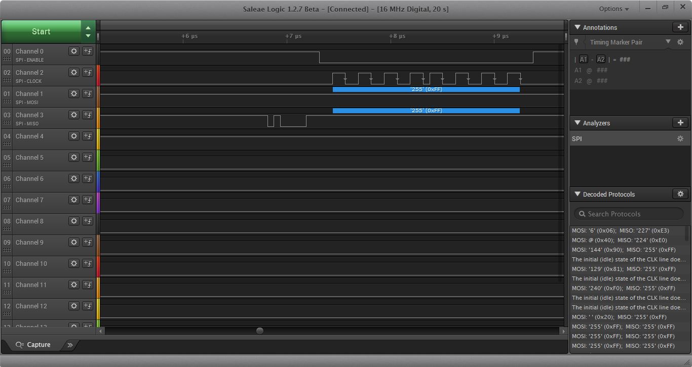
I am using the ADS1220 with the TMS320C5535 ezDSP and right now I am having trouble reading the data back via spi. We are using a logic analyzer to confirm the two devices are communicating via SPI but it seems that no matter what I keep reading 255(FFh) after sending the start command, 08h. I'm almost positive I am writing to the SPI tx buffer correctly because I see the different config values that I've set on the MOSI channel on the logic analyzer. Could someone maybe point me in the right direction and let me know what I might be overlooking. Below is the code I am using to setup and test the adc and SPI comms which is just me trying to adapt and implement the pseudo code example in the ADS1220's documentation. Additionally, I've attached some screenshots of what I am seeing on the logic analyzer. Hopefully that helps as well.
RECOMMENDED PSEUDO CODE :
Delay to allow power supplies to settle and power-up reset to complete; minimum of 50 μs;
Configure the SPI interface of the microcontroller to SPI mode 1 (CPOL = 0, CPHA = 1);
If the CS pin is not tied low permanently, configure the microcontroller GPIO connected to CS as an output;
Configure the microcontroller GPIO connected to the DRDY pin as a falling edge triggered interrupt input;
Set CS to the device low;
Delay for a minimum of td(CSSC);
Send the RESET command (06h) to make sure the device is properly reset after power-up;
Delay for a minimum of 50 μs + 32 · t(CLK);
Write the respective register configuration with the WREG command (43h, 08h, 04h, 10h, and 00h);
As an optional sanity check, read back all configuration registers with the RREG command (23h);
Send the START/SYNC command (08h) to start converting in continuous conversion mode;
Delay for a minimum of td(SCCS);
Clear CS to high (resets the serial interface);
Loop
{
Wait for DRDY to transition low;
Take CS low;
Delay for a minimum of td(CSSC);
Send 24 SCLK rising edges to read out conversion data on DOUT/DRDY;
Delay for for a minimum of td(SCCS);
Clear CS to high;
}
Take CS low;
Delay for a minimum of td(CSSC);
Send the POWERDOWN command (02h) to stop conversions and put the device in power-down mode;
Delay for a minimum of td(SCCS);
Clear CS to high;
My code:
#include "csl_spi.h"
#include "csl_general.h"
#include "cslr_spi_001.h"
#include "corazon.h"
#include "ezdsp5535.h"
#include "csl_sysctrl.h"
#include <stdio.h>
#define CSL_TEST_FAILED (1)
#define CSL_TEST_PASSED (0)
#define ADS1220_CMD_RDATA 0x10
#define ADS1220_CMD_RREG 0x20
#define ADS1220_CMD_WREG 0x40
#define ADS1220_CMD_SYNC 0x08
#define ADS1220_CMD_SHUTDOWN 0x02
#define ADS1220_CMD_RESET 0x06
/* ADS1220 Register Definitions */
#define ADS1220_0_REGISTER 0x00
#define ADS1220_1_REGISTER 0x01
#define ADS1220_2_REGISTER 0x02
#define ADS1220_3_REGISTER 0x03
#define CSL_SPI_BUF_LEN (3)//(64)
#define SPI_CLK_DIV (24)
#define SPI_FRAME_LENGTH (1)
Uint16 spiWriteBuff[1];
Uint16 spiReadBuff[CSL_SPI_BUF_LEN];
Int16 spi_sample(void);
/////INSTRUMENTATION FOR BATCH TESTING -- Part 1 --
///// Define passState variable for catching errors as program executes.
///// Define PaSs flag for holding final pass/fail result at program completion.
volatile Int16 passState = 0x0001; // Init to 1. Reset to 0 at any monitored execution error.
volatile Int16 pass = 0x0000; // Init to 0. Updated later with passState when and if
///// program flow reaches expected exit point(s).
/////
void spiMain(void)
{
Int16 status;
printf("CSL SPI Internal Loopback Test\n\n");
status = spi_sample();
if(status != CSL_TEST_PASSED)
{
printf("\nCSL SPI Internal Loop back Test Failed!!\n");
/////INSTRUMENTATION FOR BATCH TESTING -- Part 2 --
///// Reseting passState to 0 if error detected here.
passState = 0x0000; // Was intialized to 1 at declaration.
/////
}
else
{
printf("\nCSL SPI Internal Loop back Test Passed!!\n");
}
/////INSTRUMENTATION FOR BATCH TESTING -- Part 3 --
///// At program exit, copy "passState" into "PaSs".
pass = passState; //If flow gets here, override PaSs' initial 0 with
///// // pass/fail value determined during program execution.
///// Note: Program should next exit to C$$EXIT and halt, where DSS, under
///// control of a host PC script, will read and record the PaSs' value.
/////
}
Int16 spi_sample(void)
{
Int16 status = CSL_TEST_PASSED;
Int16 result;
Int16 spiCount = 0;
Int16 delay;
CSL_SpiHandle hSpi;
SPI_Config hwConfig;
Uint32 data;
volatile Uint32 looper;
result = SPI_init();
if(CSL_SOK != result)
{
status = CSL_TEST_FAILED;
return (status);
}
else
{
printf ("SPI Instance Initialize successfully\n");
}
result = SYS_setEBSR(CSL_EBSR_FIELD_PPMODE, CSL_EBSR_PPMODE_1);
if (CSL_SOK != result)
{
printf("SYS_setEBSR failed\n");
return (result);
}
//see if this is the equivalent of asserting the CS
hSpi = SPI_open(SPI_CS_NUM_1, SPI_POLLING_MODE);
if(NULL == hSpi)
{
return (CSL_TEST_FAILED);
}
else
{
printf ("SPI Instance Opened successfully\n");
}
/** Set the hardware configuration */
hwConfig.spiClkDiv = SPI_CLK_DIV;
hwConfig.wLen = SPI_WORD_LENGTH_8;
hwConfig.frLen = SPI_FRAME_LENGTH;
hwConfig.wcEnable = SPI_WORD_IRQ_DISABLE;
hwConfig.fcEnable = SPI_FRAME_IRQ_DISABLE;
hwConfig.csNum = SPI_CS_NUM_1;
hwConfig.dataDelay = SPI_DATA_DLY_0;
hwConfig.csPol = SPI_CSP_ACTIVE_LOW;
hwConfig.clkPol = SPI_CLKP_LOW_AT_IDLE;
hwConfig.clkPh = SPI_CLK_PH_RISE_EDGE; //was falling edge
result = SPI_config(hSpi, &hwConfig);
if(CSL_SOK != result)
{
return (CSL_TEST_FAILED);
}
else
{
printf ("SPI Instance Configured successfully\n");
}
//jb recommended to disable loopback mode and enable EBSR
/*Enable the Internal Loopback mode*/
//#if (defined(CHIP_C5517))
// CSL_FINST(CSL_SPI_REGS->SPIDCRU,SPI_SPIDCRU_LPBK,ENABLE);
//#else
//#if (defined(CHIP_C5505_C5515) || defined(CHIP_C5504_C5514))
// CSL_FINST(CSL_SPI_REGS->SPIDC2,SPI_SPIDC2_LPBK,ENABLE);
//#endif
//#endif
for(looper = 0; looper < CSL_SPI_BUF_LEN; )
{
spiWriteBuff[looper] = 0;
if(CSL_SPI_BUF_LEN>1){
spiWriteBuff[(looper + 1)] = 0;
spiReadBuff[(looper + 1)] = 0;
}
spiReadBuff[looper] = 0;
//spiReadBuff[(looper + 1)] = 0;
looper += 2;
}
//send reset command (0x06h)
spiWriteBuff[0] = 0x0006;
/* Write the Data to the SPI*/
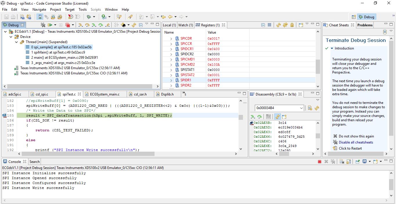
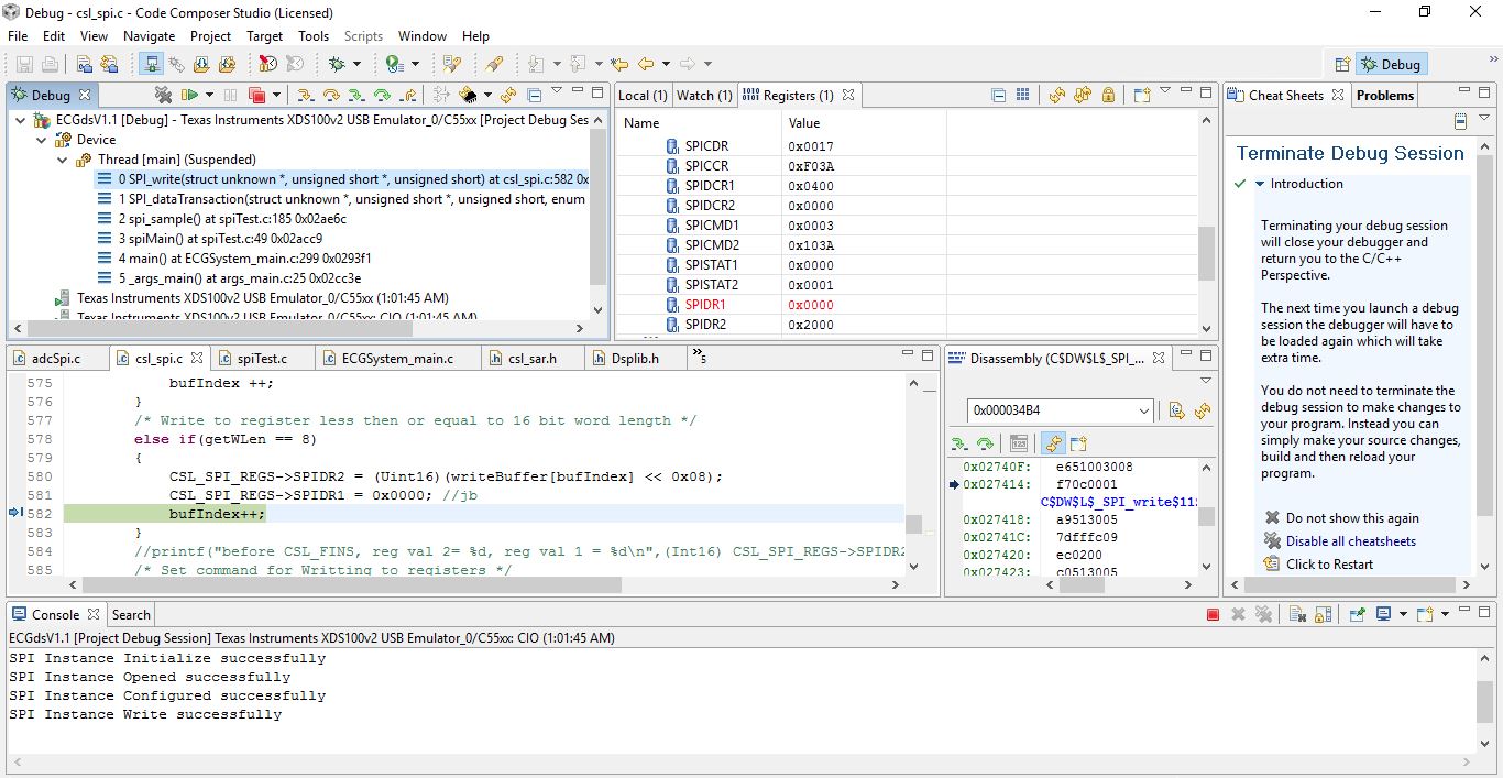
result = SPI_dataTransaction(hSpi ,spiWriteBuff, 1, SPI_WRITE);
if(CSL_SOK != result)
{
return (CSL_TEST_FAILED);
}
else
{
printf ("SPI Instance Write successfully\n");
}
EZDSP5535_waitusec(10000);
//send write reg command
spiWriteBuff[0] = (ADS1220_CMD_WREG | (((ADS1220_0_REGISTER<<2) & 0x0c) |((1-1)&0x03)));//0x0040; //write to register 0, 1byte(8bits), (0100 0000)
/* Write the Data to the SPI*/
result = SPI_dataTransaction(hSpi ,spiWriteBuff, 1, SPI_WRITE);
if(CSL_SOK != result)
{
return (CSL_TEST_FAILED);
}
else
{
printf ("SPI Instance Write successfully\n");
}
//config first buffer
// spiWriteBuff[7] = 1; //config the input to be AIN1 and negative reference to be tied to ground
// spiWriteBuff[6] = 0;
// spiWriteBuff[5] = 0;
// spiWriteBuff[4] = 1;
// spiWriteBuff[3] = 0;//config the gain to be one
// spiWriteBuff[2] = 0;
// spiWriteBuff[1] = 0;
// spiWriteBuff[0] = 1;//disable PGA
spiWriteBuff[0] = 0x0090;
// for(looper = 0; looper < 8; )
// {
// spiWriteBuff[looper] = 0x0011;
// spiWriteBuff[(looper + 1)] = 0x00AB;
// spiReadBuff[looper] = 0x0000;
// spiReadBuff[(looper + 1)] = 0x00CD;
// looper += 2;
// }
/* Write the Data to the SPI*/
result = SPI_dataTransaction(hSpi ,spiWriteBuff, 1, SPI_WRITE);
if(CSL_SOK != result)
{
return (CSL_TEST_FAILED);
}
else
{
printf ("SPI Instance Write successfully\n");
}
//send write for 2nd buffer
//send write reg command
spiWriteBuff[0] = (ADS1220_CMD_WREG | (((ADS1220_1_REGISTER<<2) & 0x0c) |((1-1)&0x03)));//0x0044; //write to register 1, 1byte(8bits), (0100 0100)
/* Write the Data to the SPI*/
result = SPI_dataTransaction(hSpi ,spiWriteBuff, 1, SPI_WRITE);
if(CSL_SOK != result)
{
return (CSL_TEST_FAILED);
}
else
{
printf ("SPI Instance Write successfully\n");
}
//config second buffer
// spiWriteBuff[7] = 1; //config the sampling frequency to 330 sps duty cycle
// spiWriteBuff[6] = 0;
// spiWriteBuff[5] = 0;
// spiWriteBuff[4] = 0; //set to normal cycle sampling mode
// spiWriteBuff[3] = 0;
// spiWriteBuff[2] = 1; //set for continuous conversion mode
// spiWriteBuff[1] = 0; //disable temp converter
// spiWriteBuff[0] = 0; //disable burnout current sensor
spiWriteBuff[0] = 0x0081;
/* Write the Data to the SPI*/
result = SPI_dataTransaction(hSpi ,spiWriteBuff, 1, SPI_WRITE);
if(CSL_SOK != result)
{
return (CSL_TEST_FAILED);
}
else
{
printf ("SPI Instance Write successfully\n");
}
//send write reg command
spiWriteBuff[0] = (ADS1220_CMD_WREG | (((ADS1220_2_REGISTER<<2) & 0x0c) |((1-1)&0x03)));//0x0048; //write to register 0, 1byte(8bits), (0100 1000)
/* Write the Data to the SPI*/
result = SPI_dataTransaction(hSpi ,spiWriteBuff, 1, SPI_WRITE);
if(CSL_SOK != result)
{
return (CSL_TEST_FAILED);
}
else
{
printf ("SPI Instance Write successfully\n");
}
//config third buffer
// spiWriteBuff[7] = 1; //config analog supply as voltage reference
// spiWriteBuff[6] = 1;
// spiWriteBuff[5] = 1; //config for 60Hz rejection filtering
// spiWriteBuff[4] = 1;
// spiWriteBuff[3] = 0;//config default
// spiWriteBuff[2] = 0;//config for default
// spiWriteBuff[1] = 0;
// spiWriteBuff[0] = 0;
spiWriteBuff[0] = 0x00F0;
/* Write the Data to the SPI*/
result = SPI_dataTransaction(hSpi ,spiWriteBuff, 1, SPI_WRITE);
if(CSL_SOK != result)
{
return (CSL_TEST_FAILED);
}
else
{
printf ("SPI Instance Write successfully\n");
}
//send write reg command
spiWriteBuff[0] = (ADS1220_CMD_WREG | (((ADS1220_3_REGISTER<<2) & 0x0c) |((1-1)&0x03)));//0x004C; //write to register 0, 1byte(8bits), (0100 1100)
/* Write the Data to the SPI*/
result = SPI_dataTransaction(hSpi ,spiWriteBuff, 1, SPI_WRITE);
if(CSL_SOK != result)
{
return (CSL_TEST_FAILED);
}
else
{
printf ("SPI Instance Write successfully\n");
}
//config fourth buffer
// spiWriteBuff[7] = 0; //config default
// spiWriteBuff[6] = 0;
// spiWriteBuff[5] = 0;
// spiWriteBuff[4] = 0;//default
// spiWriteBuff[3] = 0;
// spiWriteBuff[2] = 0;
// spiWriteBuff[1] = 1;//set DREADY/DOUT when data is ready
// spiWriteBuff[0] = 0;//reserved
spiWriteBuff[0] = 0x0001;
/* Write the Data to the SPI*/
result = SPI_dataTransaction(hSpi ,spiWriteBuff, 1, SPI_WRITE);
if(CSL_SOK != result)
{
return (CSL_TEST_FAILED);
}
else
{
printf ("SPI Instance Write successfully\n");
}
//optional sanity check to read back all registers with RREG cmd(0x23h)
spiWriteBuff[0] = (ADS1220_CMD_RREG | (((ADS1220_0_REGISTER<<2) & 0x0c) |((1-1)&0x03)));//0x0023;
// /* Write the Data to the SPI*/
result = SPI_dataTransaction(hSpi ,spiWriteBuff, 1, SPI_WRITE);
if(CSL_SOK != result)
{
return (CSL_TEST_FAILED);
}
else
{
printf ("SPI Instance Write successfully\n");
}
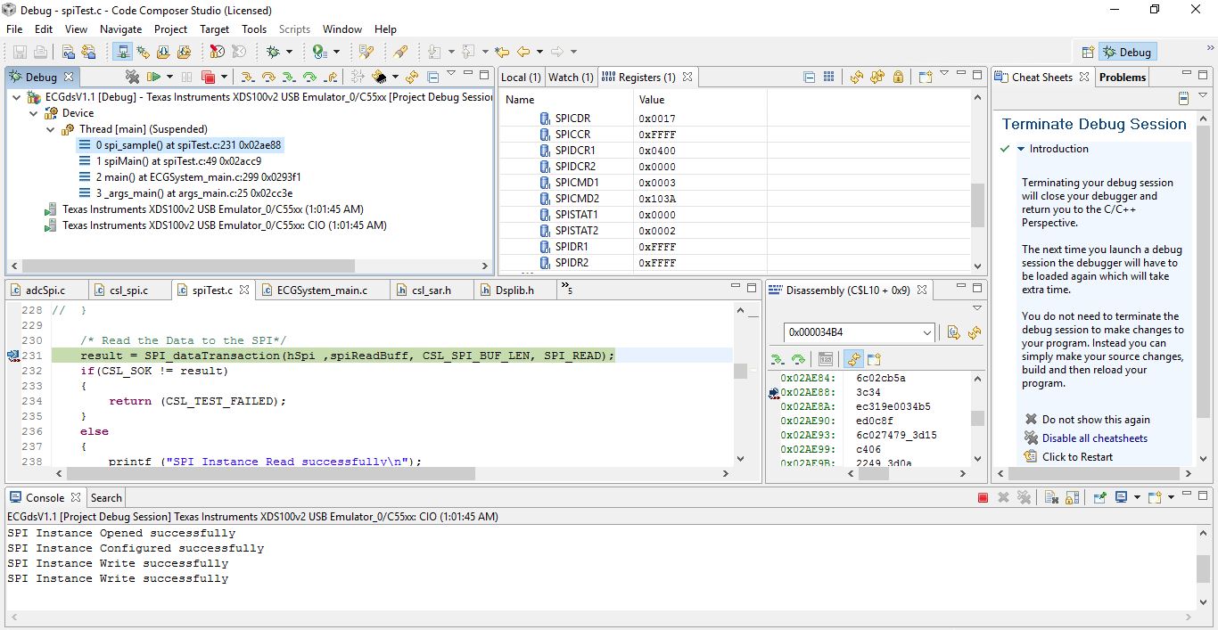
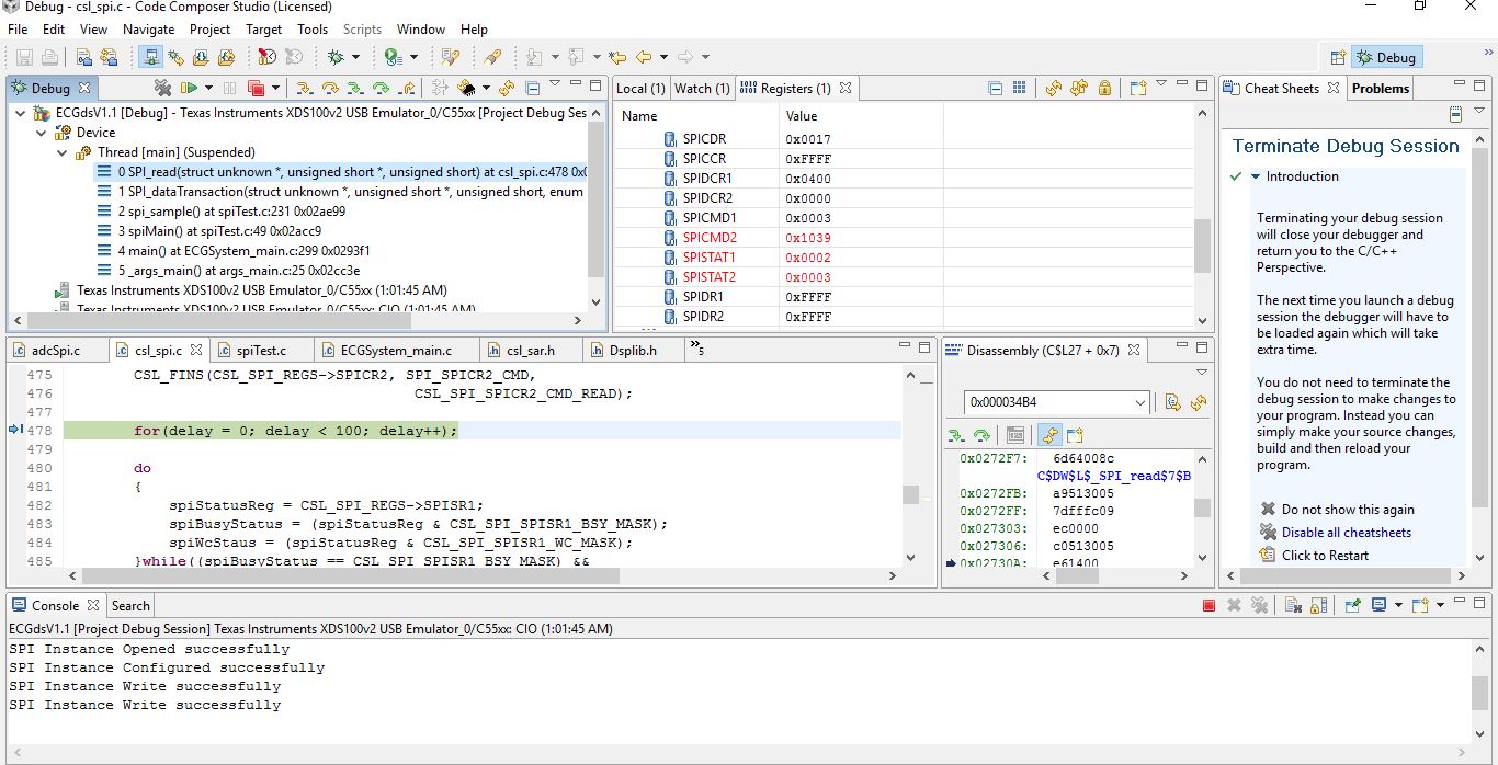
result = SPI_dataTransaction(hSpi ,spiReadBuff, CSL_SPI_BUF_LEN, SPI_READ);
if(CSL_SOK != result)
{
return (CSL_TEST_FAILED);
}
else
{
printf ("SPI Instance Read successfully\n");
}
spiWriteBuff[0] = (ADS1220_CMD_RREG | (((ADS1220_1_REGISTER<<2) & 0x0c) |((1-1)&0x03)));//0x0023;
// /* Write the Data to the SPI*/
result = SPI_dataTransaction(hSpi ,spiWriteBuff, 1, SPI_WRITE);
if(CSL_SOK != result)
{
return (CSL_TEST_FAILED);
}
else
{
printf ("SPI Instance Write successfully\n");
}
result = SPI_dataTransaction(hSpi ,spiReadBuff, CSL_SPI_BUF_LEN, SPI_READ);
if(CSL_SOK != result)
{
return (CSL_TEST_FAILED);
}
else
{
printf ("SPI Instance Read successfully\n");
}
//read config register 2
spiWriteBuff[0] = (ADS1220_CMD_RREG | (((ADS1220_2_REGISTER<<2) & 0x0c) |((1-1)&0x03)));//0x0023;
// /* Write the Data to the SPI*/
result = SPI_dataTransaction(hSpi ,spiWriteBuff, 1, SPI_WRITE);
if(CSL_SOK != result)
{
return (CSL_TEST_FAILED);
}
else
{
printf ("SPI Instance Write successfully\n");
}
result = SPI_dataTransaction(hSpi ,spiReadBuff, CSL_SPI_BUF_LEN, SPI_READ);
if(CSL_SOK != result)
{
return (CSL_TEST_FAILED);
}
else
{
printf ("SPI Instance Read successfully\n");
}
//read config register 3
spiWriteBuff[0] = (ADS1220_CMD_RREG | (((ADS1220_3_REGISTER<<2) & 0x0c) |((1-1)&0x03)));//0x0023;
// /* Write the Data to the SPI*/
result = SPI_dataTransaction(hSpi ,spiWriteBuff, 1, SPI_WRITE);
if(CSL_SOK != result)
{
return (CSL_TEST_FAILED);
}
else
{
printf ("SPI Instance Write successfully\n");
}
result = SPI_dataTransaction(hSpi ,spiReadBuff, CSL_SPI_BUF_LEN, SPI_READ);
if(CSL_SOK != result)
{
return (CSL_TEST_FAILED);
}
else
{
printf ("SPI Instance Read successfully\n");
}
//send start command (0x08h)
spiWriteBuff[0] = 0x0008;
// /* Write the Data to the SPI*/
result = SPI_dataTransaction(hSpi ,spiWriteBuff, 1, SPI_WRITE);
if(CSL_SOK != result)
{
return (CSL_TEST_FAILED);
}
else
{
printf ("SPI Instance Write successfully\n");
}
EZDSP5535_waitusec(1000);
while(spiCount<1000){
spiCount++;
// /* Read the Data to the SPI*/
result = SPI_dataTransaction(hSpi ,spiReadBuff, CSL_SPI_BUF_LEN, SPI_READ);
if(CSL_SOK != result)
{
return (CSL_TEST_FAILED);
}
else
{
printf ("SPI Instance Read successfully\n");
}
printf("readBuff = %04x\n", spiReadBuff[0]);
}
result = SPI_close(hSpi);
if(CSL_SOK != result)
{
return (CSL_TEST_FAILED);
}
else
{
printf ("SPI Instance Close successfully\n");
}
/* Compare the Data */
for( looper = 0 ; looper < CSL_SPI_BUF_LEN ; looper++ )
{
if(spiWriteBuff[looper] != spiReadBuff[looper] )
{
return (CSL_TEST_FAILED);
}
}
return (status);
}
Thanks,
Ulbert


(not sure why this happened or if it affected anything)


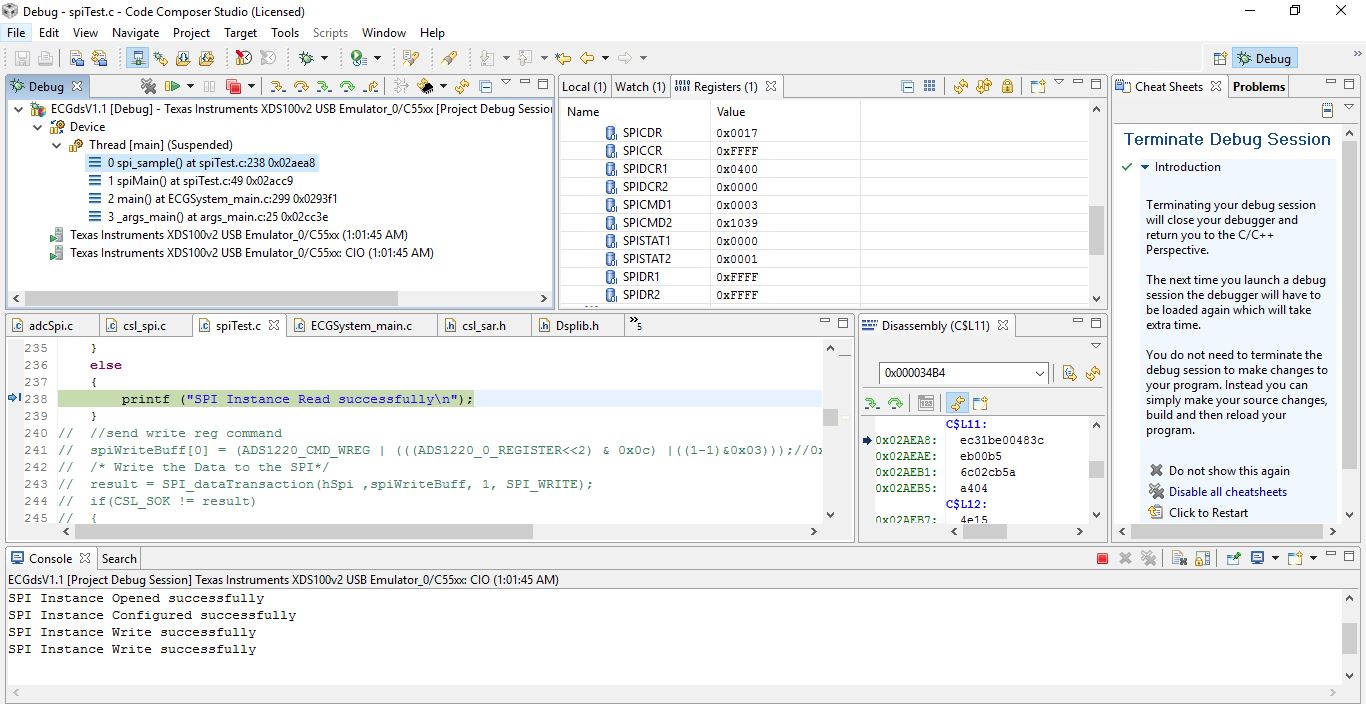
UPDATE: SPI REGISTER VALUES