This thread has been locked.

If you have a related question, please click the "Ask a related question" button in the top right corner. The newly created question will be automatically linked to this question.

U-boot SPL boot via USB problem on AM3352 custom board

Hi,

I have a custom board based on the AM3352BZCZD80.

I've also customized the u-boot in order to detect my board correctly, double checked pinmux configuration, etc. The u-boot configuration/compilation is as follows:

make ARCH=arm CROSS_COMPILER=arm-linux-gnueabihf- am335x_evm_usbspl_config

make ARCH=arm CROSS_COMPILER=arm-linux-gnueabihf-

After SPL gets running, it should reset the USB in order to use a different VID/PID, then the host stops "listening"  the ROM boot loader and starts "listening" the SPL boot.

However, for some reason, the musb-hdrc reset interrupt does not occur preventing the host from detecting the SPL's VID/PID.

This is what I get in the console (UART0):

CCCCCC
U-Boot SPL 2014.07-dirty (Apr 08 2016 - 12:44:42)
Using default environment

usb_ether
using musb-hdrc, OUT ep1out IN ep1in STATUS ep2in
MAC ec:24:b8:9b:71:10
HOST MAC de:ad:be:af:00:00
RNDIS ready
ERROR: The remote end did not respond in time.
at drivers/usb/gadget/ether.c:2396/usb_eth_init()
Problem booting with BOOTP
### ERROR ### Please RESET the board ###
CCCC

And this is what I get in my "old" board based on the AM3352BZCZ100 - which is working properly:

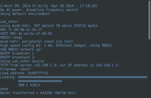
Note the messages "musb-hdrc: peripheral reset irq lost!" followed by "USB RNDIS net work up!".

What am I missing?

Thanks,

--Wendell.

  • Wendell,

    Could you please confirm what version of the SDK you are using?

    Is it the same host computer in both cases?

    Have you tried increasing the cdc_connect_timeout? This is an environment variable so you should be able to do something like "setenv cdc_connect_timout n" at the U-Boot command prompt. This should give the host PC more time to respond.

  • 1) SDK Version: no TI SDK, I'm using:
    - a customized U-BOOT (2014-07) that works with our "old" custom board.
    - arm-linux-gnueabihf version: 4.9.2-10

    2) Yes, it's the same host computer (a Linux/Debian 8.3) in both cases.

    3) I tried "setenv cdc_connect_timeout XX;", with XX = [10, 20, 30, 50] and no go.
    Note that in the error case, what is missing is the "irq lost!".
    In the host side, lsusb command shows "0451:6141 Texas Instruments, Inc." during the SPL upload, which is good so far.
    But when the SPL gets running, I would expect to see VID/PID of the SPL, but the "0451:6141 Texas Instruments, Inc." simply disappears.
  • 1) Not using TI SDK. I'm using
    - A customized U-BOOT (2014-07) that works in the "old" custom board

    2) Yes, it's the same host computer in both cases (a Linux/Debian 8.3 Core i7 PC)

    3) I've used "setenv cdc_connect_timeout XX" where XX in [10, 20, 30, 50] and no go.
  • Dear RonB,

    The problem is that, once SPL is running, the reset the USB port - in order to change the vendor ID/product ID (identifying the SPL) - does not happen. I've put some printf's in the u-boot source; and what I've found is that the USB interrupt handler does not runs in the new board.

    What could prevent this reset of the USB port?

    Who triggers this reset, by the way? The u-boot, or the ROM bootloader?
  • Wendell,

    Did you make any hardware changes to the board between revisions that might impact USB?

    I am consulting with some USB experts to get their thoughts on your questions above.

  • Wendell,

    Please add a debug code right before "error("The remote end did not respond in time.");" in usb_eth_init() to print the value of MUSB register Power and DevCtl. Please also print the 'timeout' value too.

    Please let me know if you have any problem to make the code change.

  • Ron,

    The hardware has changed from the prototype version (the board that works) and the production version (the board that does not work).
    Roughly speaking, changes are: AM3352BZCZD80 instead of AM3352BZCZ100, and additional protection circuitry.
    Further details on that are being developed in private.

    Right now, I'm adding some debugs/print's as requested by Bin Liu.
    More info/results coming soon.

    Thanks.
  • Bin Liu,

    I was unable to put the debug code exactly where you asked for.  I couldn't determine how to get musb struct inside usb_eth_init().

    However, I enabled the debug code in musb_core.c | musb_stage0_irq(), which prints what you've requested:

    Output from the production board:

    ====================================================

    U-Boot SPL 2014.07-dirty (Apr 11 2016 - 16:16:04)

    is_bone

    musb_init_controller

    CPU Freq: 800 MHz

    No AC power, disabling frequency switch

    Using default environment

    usb_ether

    musb_start: mregs addr: 0x47401400

    musb_start: INTR ENABLED

    musb_start: peripheral is enabled

    musb_start: MUSB_DEVCTL_VBUS active

    using musb-hdrc, OUT ep1out IN ep1in STATUS ep2in

    MAC ec:24:b8:9b:71:10

    HOST MAC de:ad:be:af:00:00

    RNDIS ready

    ** IRQ peripheral usb0001 tx0000 rx0000

    <== Power=e0, DevCtl=99, int_usb=0x1

    ** IRQ peripheral usb0004 tx0000 rx0000

    <== Power=f0, DevCtl=99, int_usb=0x4

    ** IRQ peripheral usb0004 tx0000 rx0000

    <== Power=f0, DevCtl=99, int_usb=0x4

    ** IRQ peripheral usb0004 tx0000 rx0000

    <== Power=f0, DevCtl=99, int_usb=0x4

    ** IRQ peripheral usb0004 tx0000 rx0000

    <== Power=f0, DevCtl=99, int_usb=0x4

    ** IRQ peripheral usb0004 tx0000 rx0000

    <== Power=f0, DevCtl=99, int_usb=0x4

    ** IRQ peripheral usb0004 tx0000 rx0000

    <== Power=f0, DevCtl=99, int_usb=0x4

    ** IRQ peripheral usb0004 tx0000 rx0000

    <== Power=f0, DevCtl=99, int_usb=0x4

    ** IRQ peripheral usb0004 tx0000 rx0000

    <== Power=f0, DevCtl=99, int_usb=0x4

    ** IRQ peripheral usb0001 tx0000 rx0000

    <== Power=f0, DevCtl=99, int_usb=0x1

    ERROR: The remote end did not respond in time.

    at drivers/usb/gadget/ether.c:2396/usb_eth_init()

    cdc_connect_timeout: 15000

    Problem booting with BOOTP

    ### ERROR ### Please RESET the board ###

    ===================================================

    I'm now preparing the same setup in the prototype board in order to compare the outputs.

    Hope this is enlightening.

    Thanks.

  • Bin Liu,

    This is the debug output from the prototype board (which works):

    U-Boot SPL 2014.07-dirty (Apr 11 2016 - 16:16:04)

    is_bone

    musb_init_controller

    CPU Freq: 1000 MHz

    No AC power, disabling frequency switch

    Using default environment

    usb_ether

    musb_start: mregs addr: 0x47401400

    musb_start: INTR ENABLED

    musb_start: peripheral is enabled

    musb_start: MUSB_DEVCTL_VBUS active

    using musb-hdrc, OUT ep1out IN ep1in STATUS ep2in

    MAC 7c:66:9d:2c:0e:c7

    HOST MAC de:ad:be:af:00:00

    RNDIS ready

    ** IRQ peripheral usb0001 tx0000 rx0000

    <== Power=e0, DevCtl=99, int_usb=0x1

    ** IRQ peripheral usb0004 tx0000 rx0000

    <== Power=f0, DevCtl=99, int_usb=0x4

    ** IRQ peripheral usb0000 tx0001 rx0000

    csr 0001, count 8, myaddr 0, ep0stage idle

    musb-hdrc: peripheral reset irq lost!

    ** IRQ peripheral usb0000 tx0001 rx0000

    csr 0000, count 0, myaddr 0, ep0stage out/status

    ** IRQ peripheral usb0004 tx0000 rx0000

    <== Power=f0, DevCtl=99, int_usb=0x4

    ** IRQ peripheral usb0000 tx0001 rx0000

    csr 0001, count 8, myaddr 0, ep0stage idle

    ** IRQ peripheral usb0000 tx0001 rx0000

    csr 0000, count 0, myaddr 0, ep0stage in/status

    ** IRQ peripheral usb0000 tx0001 rx0000

    csr 0001, count 8, myaddr 73, ep0stage idle

    ** IRQ peripheral usb0000 tx0001 rx0000

    csr 0001, count 8, myaddr 73, ep0stage out/status

    ** IRQ peripheral usb0000 tx0001 rx0000

    csr 0001, count 8, myaddr 73, ep0stage out/status

    ** IRQ peripheral usb0000 tx0001 rx0000

    csr 0000, count 0, myaddr 73, ep0stage in

    ** IRQ peripheral usb0000 tx0001 rx0000

    csr 0001, count 8, myaddr 73, ep0stage out/status

    ** IRQ peripheral usb0000 tx0001 rx0000

    csr 0001, count 8, myaddr 73, ep0stage out/status

    ** IRQ peripheral usb0000 tx0001 rx0000

    csr 0001, count 8, myaddr 73, ep0stage out/status

    ** IRQ peripheral usb0000 tx0001 rx0000

    csr 0001, count 8, myaddr 73, ep0stage out/status

    ** IRQ peripheral usb0000 tx0001 rx0000

    csr 0001, count 8, myaddr 73, ep0stage out/status

    ** IRQ peripheral usb0000 tx0001 rx0000

    csr 0001, count 8, myaddr 73, ep0stage out/status

    high speed config #2: 2 mA, Ethernet Gadget, using RNDIS

    Thanks.

  • Thanks for the log. I don't think the RESET interrupt (int_usb=0x4) should happen more than once. I will look at the log more tomorrow.

    Our USB HW expert is out, so I am unable to get his comments, but I don't think it is right to add the new component on DP/DM as in your production board. Can you please try to remove it and test again?

  • Wendell,

    If you have a USB protocol analyzer, please connect it to the bus to capture the bus trace. I suspect the new component on the DP/DM causes signal integrity, which causes MUSB is unable the receive the very first SETUP packet from the USB host.
  • Hi,

    We removed the component ant test again without sucess.

    Tks.
  • Hello,

    We already removed the component without sucess. We don´t have a USB analyzer right way to use.
    We have other USB product with the same hardware circuit and working fine. Can you tell me why the Sitara USB is sensitive to this component?

    Tks.
  • Remove FB10 and connect the USB connector directly to DGND with a low impedance conductor.

    Regards,
    Paul
  • FB10 removed: NO SUCESS

    Regards,

    Rofino

  • Is there a diference between the two stages of boot that could be an explanation why USB hardware can be involved? Some type of degration? Diferent transmition rates?

    Regards,
    ROFINO
  • The issue was solved!

    We had an error in hardware configuration. We have two options for ESD protection associated with chasssi ground plane and digital ground plane using different components assembly. We assembled the board wrong, inserting a component in USB Data Line referenced with digital ground plane.
    We suspected the different transmission rates between the two stages changed the dynamic model of the board with this component inserted with two distinct behaviors.

    Thank you for all the support.

    Best Regards.
    ROFINO
  • Rofino,

    Glad the issue is solved. Thanks for the update.

    If I remember it correctly, ROM uses full-speed mode, but SPL uses high-speed mode.

    The debug log Wendell posted yesterday shows that after received bus reset, MUSB is unable to receive the very first SETUP packet (GET_DESCRIPTOR) from the host, the EP0 interrupt does not happen.

    Is it possible to use a scope to probe the bus at the point closing to am335x? Please probe DP/DM and VBUS lines.

    Is the USB line trace routing the same in both prototype and production boards?

  • Hello,

    We continue to work with u-boot in our custom board with AM335SBZCZD80. Now we are facing a behaviour related to running the u-boot on different host plataforms, with the same board configuration.

    • BOARD CONFIGURATION 1 (VBUS BYPASS CAPACITOR=10uF 10V X5R 10% 0603 - R162,R230,R282,R280,R160: DO NOT INSERTED)
    1. HOST DELL OPTIPLEX 780 REAR USB PORT: u-boot OK
    2. HOST DELL PRECISION M4500 USB PORT: u-boot fail during the start of the first stage (SPL/MLO) with message "Waiting for SPL"

    • BOARD CONFIGURATION 2 (VBUS BYPASS CAPACITOR=10uF 10V X5R 10% 0603 - D4,L10,D11,D12,D13,FB10,D14,D15: DO NOT INSERTED)
    1. HOST DELL OPTIPLEX 780 REAR USB PORT: u-boot fail during the start of the second stage with message "close uboot file - Cannot release interface! error = -4"
    2. HOST DELL PRECISION M4500 USB PORT: u-boot OK

    We are suspecting problems during transitions on USB controller related to VBUS capacitance. We are a little confused about the value of capacitance to be inserted in our project for u-boot correct performance. On our product, we expect to use the board as USB peripheral.

    Thanks in advance,

    ROFINO

  • This post will be merged with your original thread.
  • The USB specification requires the VBUS capacitor on a USB peripheral to be between 1uF and 10uF.

    Regards,
    Paul
  • Paul,

    Do you have any explanation why we have two different USB behaviour using u-boot?

    Regard,
    Rofino
  • Not me. I'm not a software person.

    Is there another thread that descibes the problem better? If not, provide as much information as possible and I will ask our USB software guy to review.

    Regards,
    Paul
  • Rofino,

    Fabio Rofino said:
    HOST DELL PRECISION M4500 USB PORT: u-boot fail during the start of the first stage (SPL/MLO) with message "Waiting for SPL"

    Is it the exact message? I don't see anywhere in uboot to print this message.

    I don't think we have the full schematics to understand the difference of the two configurations.

    We need more information to understand the problem. USB bus analyzer trace would help to understand where the error happens. The scope probing of DP/DM & VBUS pins also helps.

  • Bin Liu,

    This message is printed by our custom "usb-flasher program" on the host side. This program uses libusb and emulates all protocol stack need (RNDIS, ARP, UDP, BOOTP, TFTP), to boot the board via USB. This message is printed after the ROM boot resets the usb port and, then, it waiting by the SPL appears as a specific VendorID/ProductID via an USB enumeration.

    The strange thing is: when this program runs in other (random) Linux host of our lab, it works. And even in the same host, it doesn't work depending of the USB port (e.g. USB ports in the front-side works, while USB ports on the back-side of the same host doesn't.)

    We'll try provide more useful information. 

    Thanks,

  • Bin,

    We provided the last version of our schematics on internal e-mail.

    Regards,

    ROFINO

  • When failed with a host port, please check the PC dmesg log, which might have information of enumeration failure, which could give a little information. But please work on getting bus protocol trace and probing screenshots.

  • Hello,

    We made adjustaments on VBUS capacitance wtih the ESD configuration without TVS and diodes.

    The system is working fine now.

    ROFINO

  • Hello,

    We continue to work with the bring-up of our product.
    Now we are facing an issue with RTC.
    We need to configure the operation of RTC using internal clock source (32KHz). We are working with our software team to provide the solution and until now we don’t have any success.
    Below, some questions and directions we are trying to follow.
    a) All erratas about RTC was verified, specially the Advisory 1.05 about PWRONRSTn.
    b) Is there any restriction to use the internal clock for RTC?
    c) Is there any direction on linux we need to follow beside the classic clock mapping configuration?

    Thanks in advance.
  • Hello.

    We made some advance follow the instruction described on chapter 20.3.4 of Sitara Technical reference Manua (SPRUH73M), specially applying step 4.

    Best regard.
  • Hello Guys,

    After 3 days of struggle, and after carefully reading of 20.3.4 section of the SPRUH73M doc, I've finally figured out what happened: I was trying to write RTC registers without unlocking them.

    Now RTC is working with internal clock source and is powering down the PMIC properly.

    Thanks.