


I made three 6748 board and now I'm testing them. Name them as board_A, board_B and board_C.
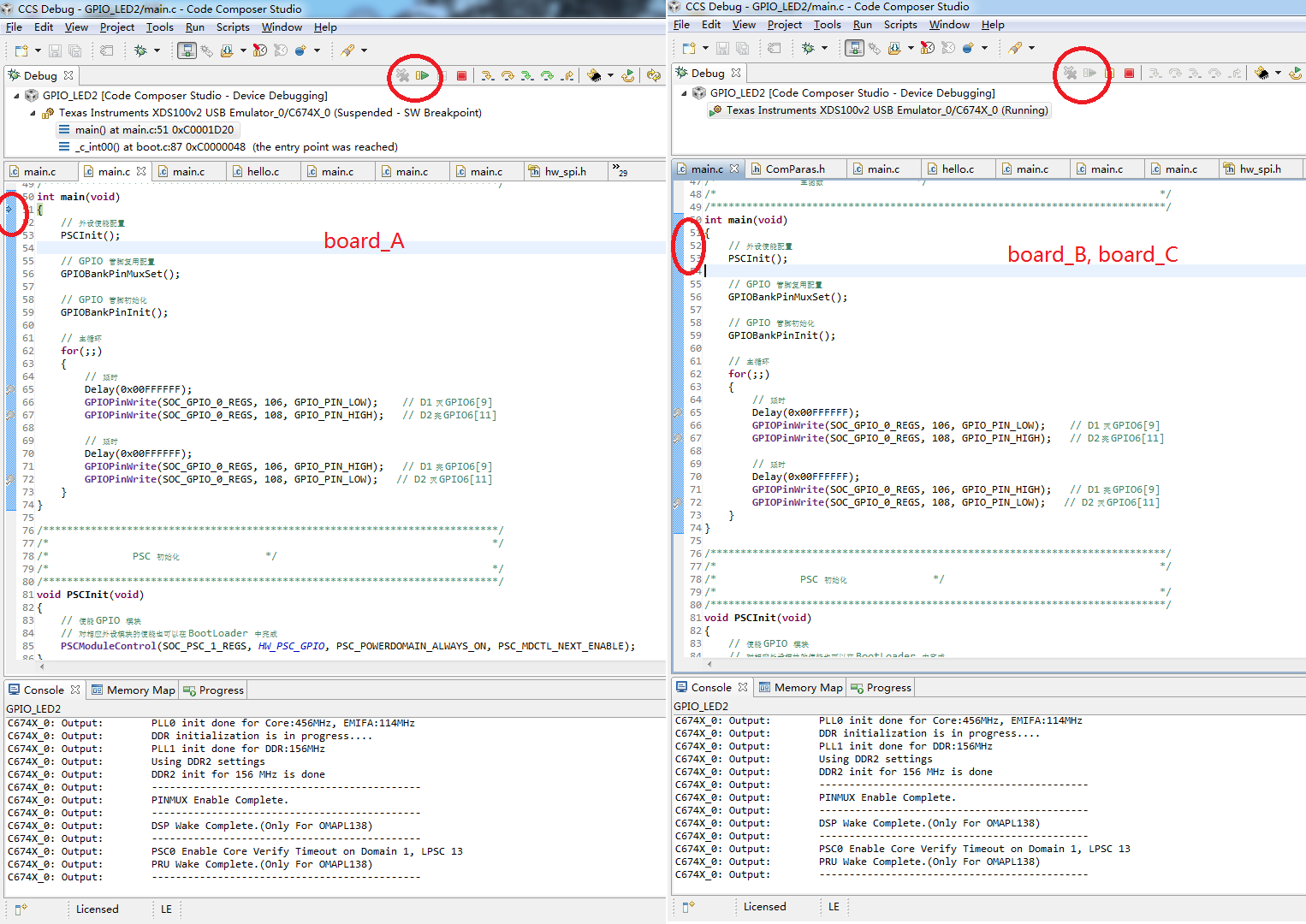
board_A is alright, I can debug it in CCS as shown in the following figure.
But board_B and board_C cannot get into debug state in CCS, as shown in the right of the figure.
I monitored the current of the boards (testing with a LED program):
1. When the boards are not programmed, the three boards all takes 72mA.
2. When board_B and board_C are programmed, they both takes 210mA. The LED is not blinking.
3. When board_A is programmed, it get into the debug mode and the break point stop at the first line of main(), the current is 180mA.
When I press F8 to let the program run, the current rise to 220mA (equal to the current in 2.). The LED is blinking.
The voltages (1.3V/1.8V/3.3V) on the three are all right.
What's the possible cause of this problem?
Thank you.
Now, I find that the following programs cannot get into debug mode for board_B and board_C:
1) programs use GPIO
2) programs use SPI
3) programs use external nandflash
and the following programs can get into debug mode for board_B and board_C:
1) memorybench(including nonchip memory and external DDR(1.8V))
2) MMCSD
So, I used to think there maybe something wrong with the 3.3V. I monitered the 3.3V waveform of the three boards, I think they are all normal.
The 3.3V waveform of board_B is shown below:


