


Hello folks. We have used the AM335x in a hardware design for an arbetrary waveform module (mostly based on the ICEv2.1). Presently, we have the board properly playing back waveform data on 8 channels using the McASP. We use the following playback design:
- Data is loaded from the SD card into a series of 8 individual waveform buffers in the heap.
- DMA to McASP is set up with a pair of ping-pong buffers and linked DMA parameters to spool the data directly from the already-sorted buffer to the audio DAC. On parameter swap, an ISR is fired to load the buffer that is not being used. Buffer length is sufficient for 5ms of playback at 192 kHz.
- During initial setup, or when the ISR is fired, we calculate a series of linked transfers (between 8 and 16 DMA parameters, depending on whether we are wrapping around to the beginning again) to sort the data from the individual waveform buffers (which may be different lengths) into the corresponding packed order in the playback ping-pong buffer
As per above, if we load the wave data once and then start playback, everything works properly. However, we wanted to extend to dynamically generate a wavefile based on a user-defined frequency/period/etc. over EtherCAT, which can change at any time. The approach I came up with was:
- Create a 'scratch area' for the wave data; initially 3 buffer widths wide (extended to 4 as I debugged further). This data is sorted into the ping pong buffers uses the exact same algorithm as complete wave files above.
- When the ISR sets up the DMA transfers for the wave playback, set a flag to tell the foreground EtherCAT frame (at 1ms framerate) to load more data. It already has to keep track of where the NEXT update is to start from.
- As soon as the foreground thread sees the flag, it will clear the flag calculate the next slice of the waveform in the scratch area. It will be writing the segment ahead of what is used for playback, so there should be no overlap. I later changed it to work two buffers ahead of DMA to be paranoid. Since the foreground thread runs at 1ms, it is essentially guaranteed to be able to complete this calculation before the next 5 ms ISR.
What I'm actually seeing happening is only some variable-sized segments of my waveform actually get transferred correctly from my scratch area to the ping-pong buffer. The corrupted areas appear to keep the initial data I loaded on startup. I also noticed that when the updates were occurring, it was always the same sections of the waveform that would update; the sections left at the default would ALWAYS stay at default.
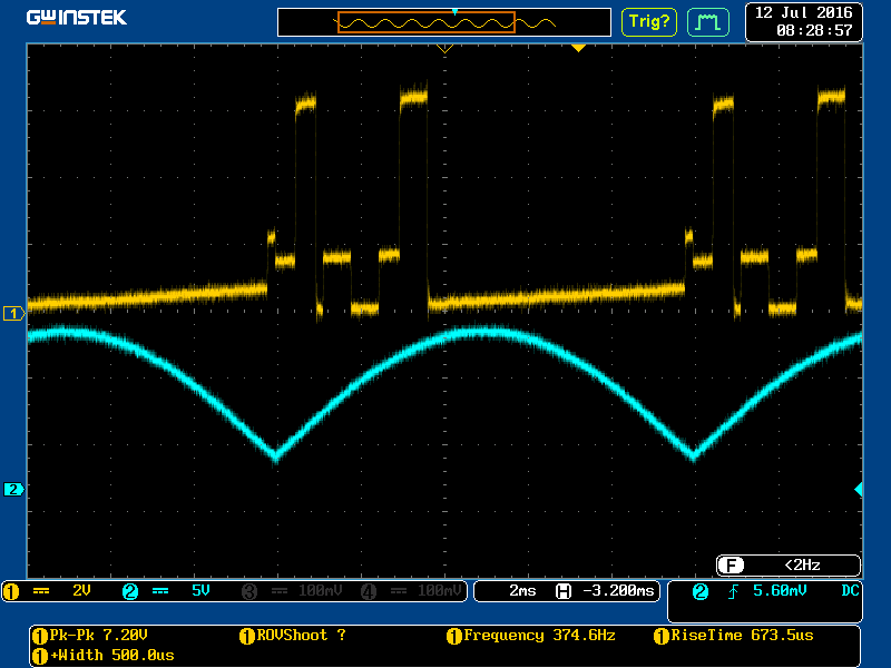
As part of my testing, I actually slowed down my update routine so I would only write the next segment to the scratch area once a second, while repeatedly DMAing the 'stable' 4-buffer segment of the waveform. This has no effect on the behaviour. The following is an oscilloscope capture of the output waveform (yellow) while a reference 50 Hz pre-calculated sine wave is being played on channel 2 (blue).
The test waveform is a very simple sawtooth wavefile which will count from 0 to 19200 at a rate of 1 per sample, then loop back to zero. You can see above the initial section of the waveform is mostly present, with the 'correct' updated waveform only partially visible. Some segments are more complete than others, but the general trend is visible.
I stopped the code with the debugger and inspected both the waveform buffer and the playback buffers.A cute side-effect of the fact that playback is strictly ping-pong DMA is that the output would continue to loop on the contents of the two buffers. Here is the reference scope trace of these two buffers to correspond with the later plots I generated of the data dumps:
The sine wave actually provides a very good guide for the buffer boundaries; the rising section of the SINE is one buffer, while the falling is another. I've aligned those with the scope division lines. You will see that the first buffer has a large number of glichy data points, but it does appear to contain more of the updated waveform. At first glance, the second buffer appears to contain almost none of the waveform, until you notice that the one spike is just before the end of playback; that is the only data sample correctly updated in that part of the file.
The waveform buffer exactly matches what I wrote into it. The two ping-pong buffers, however, *mostly* match the output. I say mostly, because there are blocks of the data that the debugger appeared unable to read and wrote zeroes. Viewing in a memory window, no errors were reported; it just looked like an 'actual' zero. The debugger also seemed to read zeroes for ALL channels in the output buffer, not just the one I was having problems generating. However, with the scope data to prove what actually went to the Audio DAC -- especially the uninterrupted sine segment -- I can confirm that the data must have been there still.

Since the waveform contains all 4 buffer widths, it also contains data that has not yet been loaded to the ping-pong buffers, as illustrated in the plot. I also combined both ping-pong buffer contents into a single plot to show a direct comparison with the oscilloscope view. I'm also attaching the excel file with for reference; that will contain a highlight where the buffer boundary exists.
So, any ideas what might be happening? This seems to be to be something to do with cache, but I'm not sure how this ends up with the CPU and the DMA getting a different view of the same location in memory. The error appears to persist as well; when it was slowed down to 1 second writes, the DMA would have plenty of additional transfers to get the written data, but always saw the same result.
I will also be added a second post with specific code examples for the above architecture. This post may not get completed until tomorrow however.

